Inputs and outputs, I/o connector pin diagram, Spd acc/dec – Applied Motion BD10-H4-AH User Manual
Page 14
14
BD5/10 Drive Hardware Manual
920-0065D
2/14/2014
Inputs and Outputs
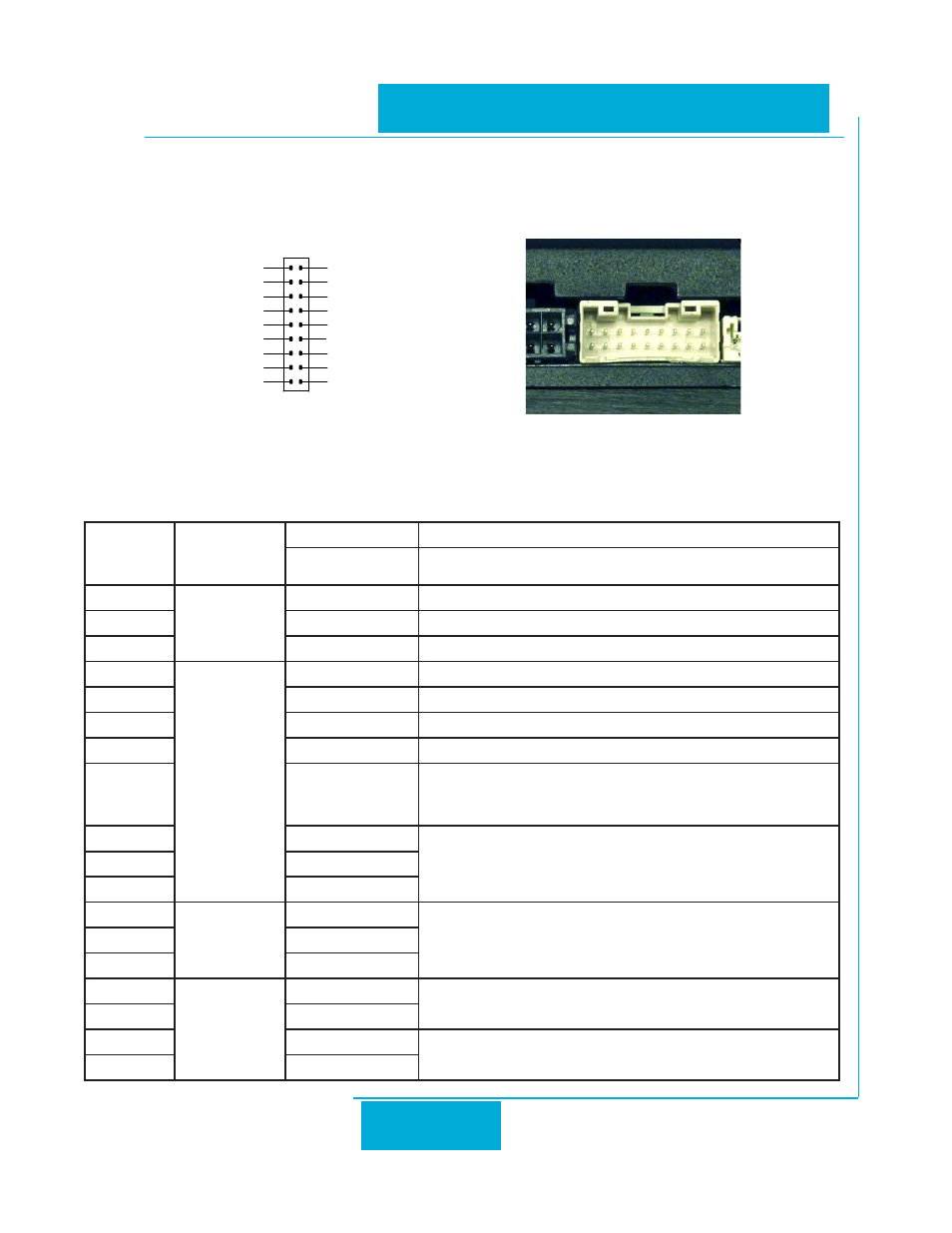
All inputs and outputs are available on one dual-row, 18-pin connector (2 mm pitch). See page 29 for mating
connector recommendations. The pin-outs are as follows:
I/O Connector Pin Diagram
INPUT & OUTPUT TABLE
PIN NUM
SIGNAL
TYPE
SIGNAL NAME
FUNCTION
BASIC
BASIC
1
POWER
SUPPLY
5V
The drive provides users with up to 50mA +5V supply
2
GND
External control signal GND
18
INCOM
External opto-coupler power input.
3
INPUT
CW/CCW
controls motor direction of rotation. open=CW.
5
STMD
Stop mode select
7
EN/RE
Motor enable/disable. It can be used for alarm reset as well.
9
SPST
Internal/external speed select
11
STP
Start/Stop command input. See next section for steps to test the motor
using the internal voltage supply as a command source (SW1=ON;
SW2=OFF).
13
M0
For multi-speed operation, the M0, M1, M2 signals are used in combina-
tion.
15
M1
17
M2
12
ANALOG
INPUT
5V
Used to command speed when SPEED-SET input is closed. 5V = 4500
rpm
14
AIN
16
AGND
4
OUTPUT
FLT+
Fault output
6
FLT-
8
SPO+
Output closes when motor reaches target speed +/- 200 rpm
10
SPO-
1
3
5
7
9
11
13
15
17
2
4
6
8
10
12
14
16
18
INCOM
AGND
AIN
FLT-
SPO-
SPO+
FLT+
GND
5V
M2
M1
M0
STMD
SPST
EN/RE
CW/CCW
5V
STP
CN4
SPD
ACC/DEC