Programmable outputs, 25 bluac5-si hardware manual – Applied Motion BLuAC5-Si User Manual
Page 25
25
BLuAC5-Si Hardware Manual
920-0035E
12/10/2014
Programmable Outputs
The BLUAC5-Si drives feature seven digital outputs. Y1, Y2 and Y3 (located on the IN/OUT
1 connector) can be dedicated to specific, automatic drive signals, or they can be used as a
general purpose, programmable outputs.
Y1/Brake: can control an electric brake relay, automatically releasing and engaging as the
drive requires. A small external power relay is required when a brake is used. See App, Note
17 for details. Y2/ In Position: can be used to indicate that the drive has achieved a desired goal, such
as a target position.
Y3/Fault: can be configured to open or close when a drive fault occurs. The 7 segment
status LED also provides a visual indication of error codes.
OUT1 - OUT4 on the IN/OUT 2 connector are always general purpose, programmable out-
puts, controlled by Set Output instructions.
The outputs can be used to drive LEDs, relays and the inputs of other electronic devices like
PLCs and counters.
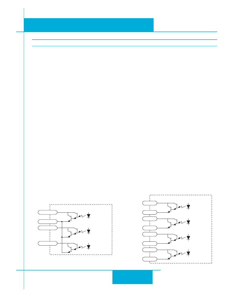
Outputs Y1, Y2 and Y3 are single ended and can only “sink” current. The COM terminal
must be tied to power supply (-).
OUT1 - OUT4 have the “+” (collector) and “-” (emitter) terminals of each transistor separately
available at the connector. This allows you to configure each output for current sourcing or
sinking.
Diagrams of each type of connection follow.
Do not connect the outputs to more than 30VDC.
The current through each output terminal must not exceed 100 mA.
inside IN/OUT 1
Y1/BRAKE
YCOM
Y2/INPOSN
Y3/FAULT
14
17
16
15
inside IN/OUT 2
OUT1+
OUT1-
OUT2+
OUT2-
OUT3+
OUT3-
OUT4+
OUT4-
20
19
18
22
21
24
25
23