3 installation/connections, 1 connecting the power supply – Applied Motion TXM24Q-1AG User Manual
Page 11
11
Rev. D
920-0087
TXM24 RS232/485 Hardware Manual
3 Installation/Connections
To meeting the IP65 protection, a suitable mating connector should be chosen.
For more information, please see the Accessories section.
3.1 Connecting the Power Supply
Use 16 to 20-gauge wire to connect the TXM24 to a power supply. It contains an internal fuse
connected to the “+” terminal that is not user replaceable. If a user serviceable fuse is desired,
install a 6.3 amp fast acting fuse in line with the “+” power supply lead.
Be careful not to reverse the wires. Reversing the connection may open the internal
fuse on the drive and void the warranty
.
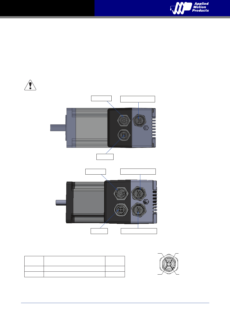
Power
Signal
Color of mating cable
Applied Motion P/N 3004-277-5M
Pin no.
V+
BN\BU
1\3
V-
WH\BK
2\4
View of motor side connector
Digital I/O
Power
RS232 COMM port1
RS485 COMM port1
Digital I/O
Power
RS485 COMM port2
2
3
4
1
J2