25 stm17 hardware manual – Applied Motion STM17C-3CE User Manual
Page 25
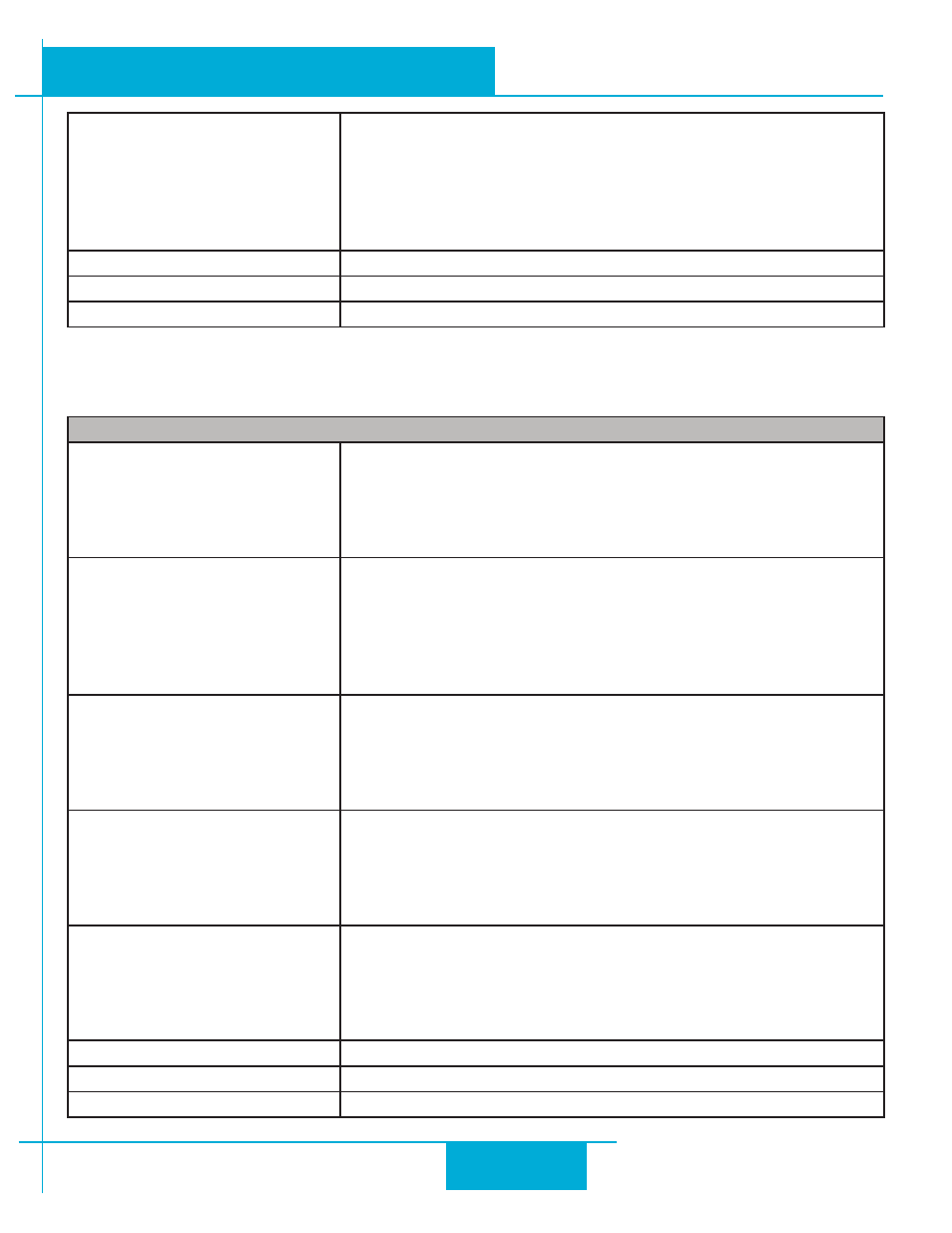
Multiple Modes Of Control
Pulse Input - Step & Direction, CW/CCW, A/B Quadrature (incre-
mental encoder
Velocity - Analog Velocity, Switch Control Velocity, Serial Command-
ed Velocity
Serial Command Language (SCL)
Stored Program Execution (Q models only)
Noise Filtering
Programmable hardware digital noise filter, software noise filter
Encoder Feedback
Optional 4000 counts/rev encoder feedback
Non-Volatile Storage
Configurations are saved in FLASH memory on-board the DSP
inPuts And outPuts
Step Input
STEP +/-
Inputs: optically isolated, 5-24 volts, minimum pulse width 250 ns.,
maximum pulse frequency 3 MHz. Max current draw 12mA.
Functions: Step, CW Step, A Quadrature, CW Limit, CW Jog, general
purpose input; adjustable bandwidth digital noise rejection filter
Direction Input
DIR+/-
Inputs: optically isolated, 5-24 volts, minimum pulse width 250 ns.,
maximum pulse frequency 3 MHz. Max current draw 12mA.
Functions: DIR, CCW Step, B Quadrature, CCW Limit, CCW Jog,
general purpose input; adjustable bandwidth digital noise rejection
filter
Enable Input
EN+/-
Inputs: optically isolated, 5-24 volts, minimum pulse width 100 us.,
maximum pulse frequency 10 KHz. Max current draw 12mA.
Functions: Enable, alarm reset, speed control, general purpose
input; adjustable bandwidth digital noise rejection filter
Output
OUT+/-
Open Collector, 30 volts, 100 mA max, maximum pulse frequency
10 KHz
Functions: Fault, brake, motion, tach, and general purpose pro-
grammable
Analog Input
AIN
Input: 0-5 volts (AIN referenced to GND). Input impedance: 30k
ohms min.
Functions: analog control modes and general purpose analog us-
age; programmable for signal range, offset, dead band and filtering
Analog Input Resolution
12 bits
Communication Interface
RS-232 or RS-422/485
Supply Output
+4.8-5 volts @ 100mA maximum
25
STM17 Hardware Manual
920-0034 rev A
9/30/2010