Stm17 inputs and outputs, 17 stm17 hardware manual – Applied Motion STM17C-3CE User Manual
Page 17
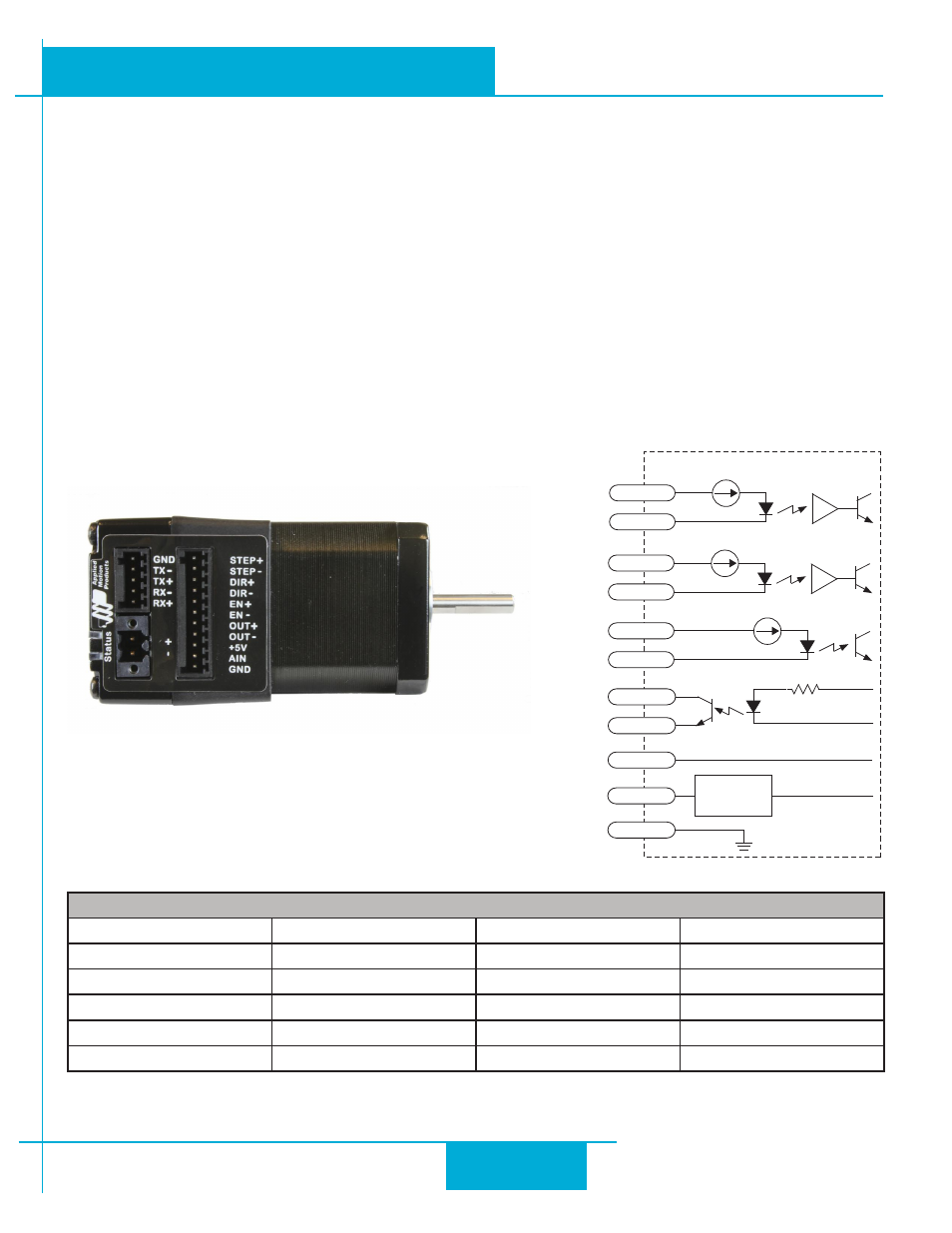
STM17 Inputs and Outputs
All STM drive+motors include three digital inputs, one analog input, and one digital output.
• STEP & DIR: 5 to 24 volt digital input signals for commanding position. When not being used for the Step & Direc-
tion function, these inputs can be used for CW & CCW Limit, CW & CCW Jogging and Run/Stop & Direction Velocity
modes. These inputs can also be connected to sensors, switches and other devices for use with SCL and Q commands
such as Wait Input, Seek Home, Feed to Sensor, If Input and others. Quadrature signals from encoders can also be used.
• EN: 5 to 24 volt software programmable input can be used for motor enable or alarm reset. This input can also be
connected to a sensor, switch and other devices for use with Wait Input, Seek Home, Feed to Sensor, If Input and other
commands.
• AIN: 0 - 5V analog input for velocity or position commands, with gain, filtering, offset and dead-band settings.
• OUT: digital output that can be set to automatically control a motor brake, to signal a fault condition, to indicate when
the motor is moving or to provide an output frequency proportional to motor speed (tach signal). The output can also
be turned on and off by SCL & Q instructions like Set Output (SO).
Connector Pin Diagram
RES
inside drive
STEP+
STEP-
I/O
Conne
ct
or
DIR+
DIR-
EN+
EN-
OUT+
OUT-
AIN
GND
Signal
Conditioning
+5V
50ma Limit
IO Functions (configure in software)
STEP (5 to 24 Volts)
DIR (5 to 24 Volts)
EN (5 to 24 Volts)
OUT (30V, 80mA)
Step Input
Dir Input
Enable Input
Brake Output
Jog CW
Jog CCW
Reset Input
Alarm Output
Limit CW
Limit CCW
Change Speed
Motion Output
Start/Stop
General Purpose
General Purpose
Tach Output
General Purpose
General Purpose
17
STM17 Hardware Manual
920-0034 rev A
9/30/2010