Testing leds & pushbutton switches, Ed in – Altera DSP Development Kit, Cyclone II Edition Getting Started User Manual
Page 26
2–16
Getting Started User Guide
Altera Corporation
DSP Development Kit, Cyclone II Edition
August 2006
Testing the Board Using the Factory Design
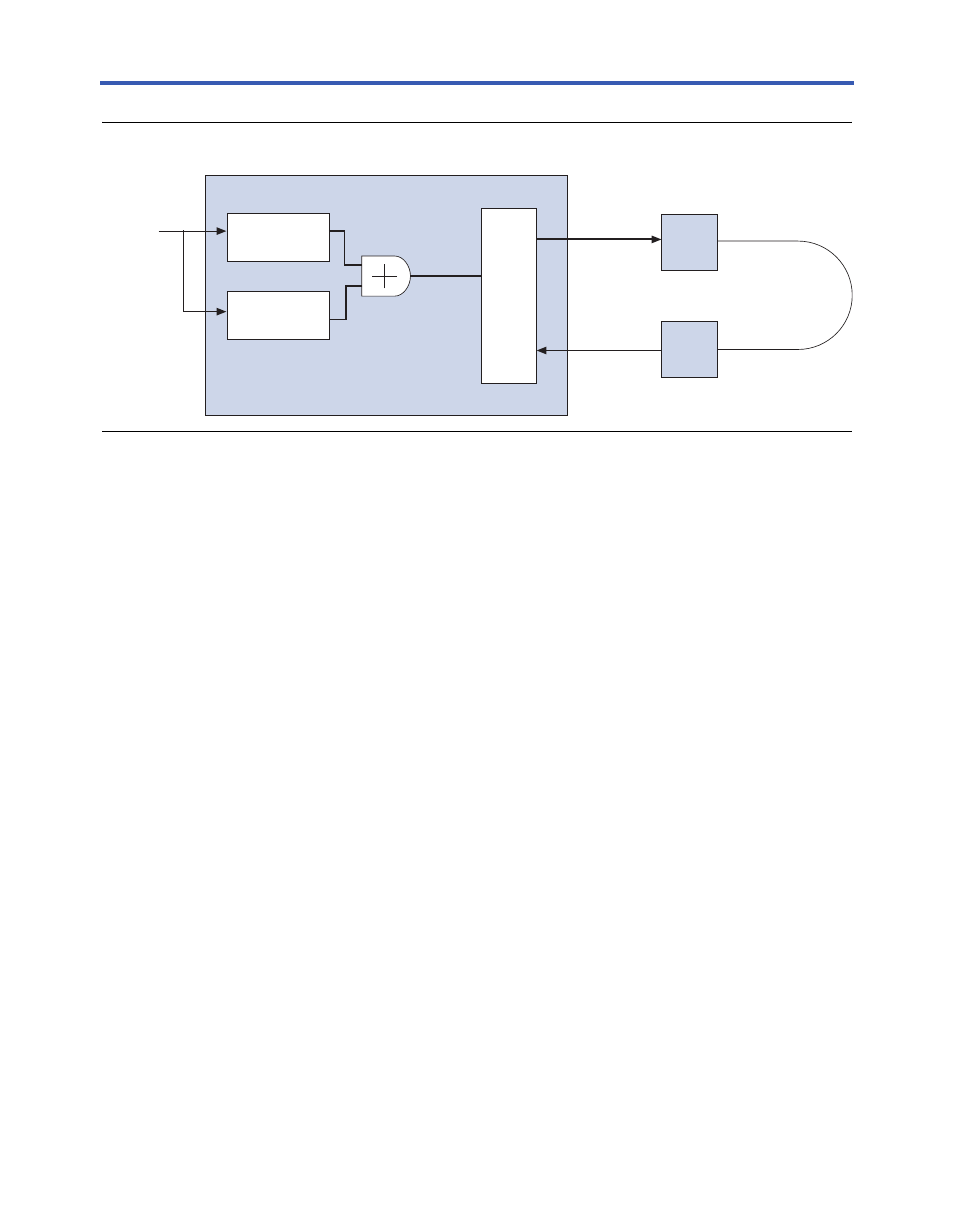
Figure 2–7. Factory Design Functional Block Diagram
1
The design files for the factory design are installed from the DSP
Development Kit, Cyclone II Edition Version 6.0.1 CD-ROM in the
directory:
<path>\CycloneII_DSP_Kit-v6.0.1\Examples\
FactoryDesign_ChA
Testing LEDs & Pushbutton Switches
In the factory design, switches SW2 through SW5 (
USER_PB3 through
USER_PB0) are connected via inverters to LEDs D9 through D6
(
USER_LED0 to USER_LED3, respectively). When a switch is pressed, the
corresponding LED turns off. You can test this functionality on the
Cyclone II DSP development board.
Performing the A/D & D/A Converter Performance Test
To test the A/D and D/A converter performance using the factory
design, follow these steps:
1.
“Configuring the Board” on page 2–17
2.
“Collecting Data Using the SignalTap II Logic Analyzer” on
page 2–20
3.
“Analyzing the Data in the MATLAB Software” on page 2–20
comb[13..0]
a2db[11..0]
100 MHz
Clock Signal
Cyclone II Device (U18)
1 MHz
Sine Wave Source
NCO
ADC A
DAC A
10 MHz
Sine Wave Source
NCO
DAC904E Device
(U25)
ADS5520 device
(U26)
SignalTap II
DAC CHANNEL A out (J31)
SMA Connector
ADC CHANNEL A in (J32)
SMA Connector
SMA Cable and
SLP-50 Low-pass
Filter
comb[13..0]