Nexen SC100 964420 User Manual
Page 8
FORM NO. L-21163-C-0808
8
16
15
14
13
12
11
9
10
+
G
W
R
B
Excitation
Voltage
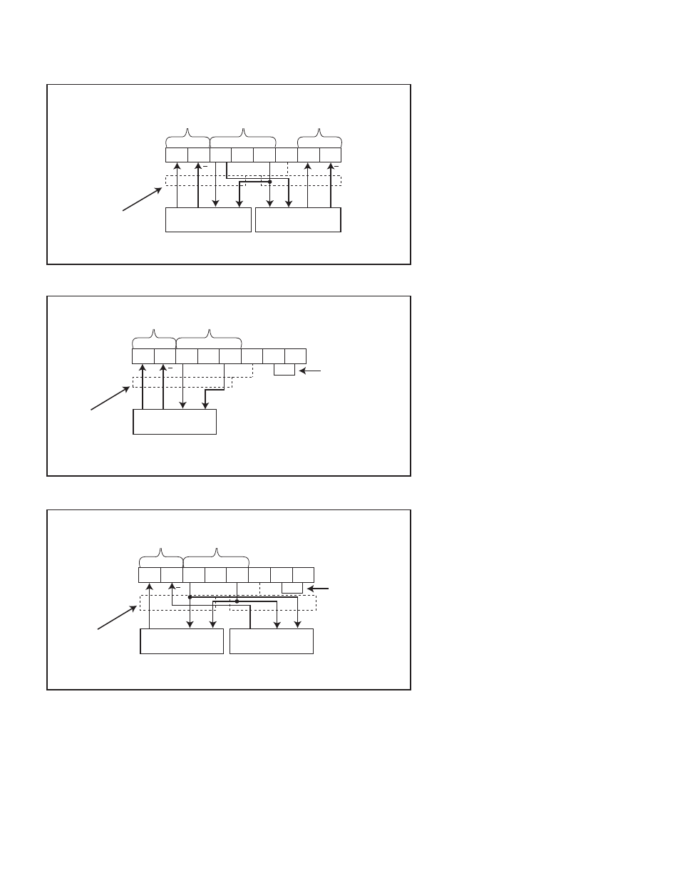
NEXEN SENSOR CONNECTIONS DIAGRAMS
W
EB
T
ENSION
S
ENSORS
Figure 6
Dual MB Sensor Wiring
16
15
14
13
12
11
9
10
+
+
G
W
R
B
B
W
G
R
Excitation
Voltage
Channel 2
Input
Channel 1
Input
No. 1 Sensor
No. 2 Sensor
Shield
Figure 7
Single MB Sensor Wiring
Channel
1 Input
No. 1 Sensor
Shield
Add jumper wire
16
15
14
13
12
11
9
10
+
W
R
B
W
R
B
Figure 8
SW Sensor Wiring
Excitation
Voltage
Add jumper wire
Channel 1
Input
No. 1 Sensor
No. 2 Sensor
Shield
NOTE: Figures 6 & 7 are for use
in normal wrap implementations.
Normal wrap is defi ned as an
increase in tension measurement
corresponds with increase of
load cell force. For reverse wrap
implementations, where an increase
in tension measurement corresponds
to a decrease in load cell force, the
White and Green wires must be
inverted. An increase in tension must
corresond to an increase in voltage
at the sensor input.
*See Note.
*See Note.
- RPS20 966611 (18 pages)
- RPS20 966753 (1 page)
- RB15B 968179 (9 pages)
- RBR25 960613 (9 pages)
- RLSSB 150-063-C-A 966304 (10 pages)
- SBPA02 964621 (13 pages)
- SBP02 964610 (14 pages)
- SBP04 964828 (2 pages)
- SBP07 965008 (14 pages)
- BSB02 964640 (13 pages)
- HG17 969000 (7 pages)
- HGP17 969011 (16 pages)
- RPS4014G-B0192T/023-EP2U 966725 (10 pages)
- RPS20G-C0140T/072-EP2U 966705 (17 pages)
- RPS25G-B,C0064T-EP1 966950 (13 pages)
- PRD1500 966903 (2 pages)
- PRD400 966904 (10 pages)
- I300 965500 (9 pages)
- MTL300-ECC-SP-32MM-20MM-150/240 976131-225 (8 pages)
- MDU-625 928600 (21 pages)
- MDO-1375 936400 (24 pages)
- Micro 856802 (9 pages)
- B-275 802871 (12 pages)
- F-450 802850 (14 pages)
- BWB 846800 (11 pages)
- XHW 810905 (10 pages)
- FMCE-625 801487 (19 pages)
- FMCE-130-19 801673 (14 pages)
- 5H50PSP-E 913044 (15 pages)
- 5H20P-E 911319 (13 pages)
- 5H50PSP 912509 (15 pages)
- 5H50P 910305 (23 pages)
- 5H30P-E 913008 (1 page)
- 5H100PSE-E 913123 (4 pages)
- 5H60P-E 913058 (14 pages)
- 5H40S 911320 (13 pages)
- 5H60PSP-SE 910440 (19 pages)
- 3-Way Valve 948809 (3 pages)
- LSCC-54 923578 (12 pages)
- TL80 911785 (10 pages)
- 4H70P 921700 (15 pages)
- DPB 15T 963900 (16 pages)
- DPB-15T 963002 (13 pages)
- DPB 11T 961900 (15 pages)
- QFE-2500 964097 (22 pages)