Sc100, Power supply connections – Nexen SC100 964420 User Manual
Page 7
7
FORM NO. L-21163-C-0808
SC100
9
10
11
12
13
14
15
16
8
7
6
5
4
3
2
1
+
+
Isolated
Output 2
Isolated
Output 1
+
Second Power
Supply
+
Power Supply
Z1
S1
Z2
S2
IND
LO
LO
SUM
OUT
MODE
HI
CH1
GAIN
HI
CH2
GAIN
CH2
OUT
CH1
OUT
PWR
VEX
V
V
SC100
9
10
11
12
13
14
15
16
8
7
6
5
4
3
2
1
+
Output 2
+
Output 1
+
Power Supply
Z1
S1
Z2
S2
IND
LO
LO
SUM
OUT
MODE
HI
CH1
GAIN
HI
CH2
GAIN
CH2
OUT
CH1
OUT
PWR
VEX
V
V
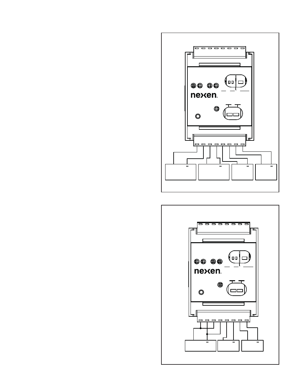
Power Supply Connections for Isolated Outputs
Power Supply Connections for Non-Isolated Outputs
POWER SUPPLY CONNECTIONS
Figure 4
Figure 5
Isolated Power Supply connections are available so that
the Control Outputs are isolated from the input circuitry.
When using Isolated Control Outputs, a second 15-24
VDC power supply is needed (See Figure 4). This
setup is most commonly used to prevent the mixing
of power supply commons together when connecting
analog control outputs to a motor drive (Refer to
SPECIFICATIONS).
If Isolated Control Outputs are not needed, the Isolated
+VDC and ISO Common must be connected to +24
VDC and DC common inputs, respectively (See Figure
5).
- RPS20 966611 (18 pages)
- RPS20 966753 (1 page)
- RB15B 968179 (9 pages)
- RBR25 960613 (9 pages)
- RLSSB 150-063-C-A 966304 (10 pages)
- SBPA02 964621 (13 pages)
- SBP02 964610 (14 pages)
- SBP04 964828 (2 pages)
- SBP07 965008 (14 pages)
- BSB02 964640 (13 pages)
- HG17 969000 (7 pages)
- HGP17 969011 (16 pages)
- RPS4014G-B0192T/023-EP2U 966725 (10 pages)
- RPS20G-C0140T/072-EP2U 966705 (17 pages)
- RPS25G-B,C0064T-EP1 966950 (13 pages)
- PRD1500 966903 (2 pages)
- PRD400 966904 (10 pages)
- I300 965500 (9 pages)
- MTL300-ECC-SP-32MM-20MM-150/240 976131-225 (8 pages)
- MDU-625 928600 (21 pages)
- MDO-1375 936400 (24 pages)
- Micro 856802 (9 pages)
- B-275 802871 (12 pages)
- F-450 802850 (14 pages)
- BWB 846800 (11 pages)
- XHW 810905 (10 pages)
- FMCE-625 801487 (19 pages)
- FMCE-130-19 801673 (14 pages)
- 5H50PSP-E 913044 (15 pages)
- 5H20P-E 911319 (13 pages)
- 5H50PSP 912509 (15 pages)
- 5H50P 910305 (23 pages)
- 5H30P-E 913008 (1 page)
- 5H100PSE-E 913123 (4 pages)
- 5H60P-E 913058 (14 pages)
- 5H40S 911320 (13 pages)
- 5H60PSP-SE 910440 (19 pages)
- 3-Way Valve 948809 (3 pages)
- LSCC-54 923578 (12 pages)
- TL80 911785 (10 pages)
- 4H70P 921700 (15 pages)
- DPB 15T 963900 (16 pages)
- DPB-15T 963002 (13 pages)
- DPB 11T 961900 (15 pages)
- QFE-2500 964097 (22 pages)