Nexen SC100 964420 User Manual
Page 10
FORM NO. L-21163-C-0808
10
16
15
14
13
12
11
9
10
+
+
+
+
16
15
14
13
12
11
9
10
+
+
Channel 1
Input
16
15
14
13
12
11
9
10
+
+
+
+
16
15
14
13
12
11
9
10
+
+
+
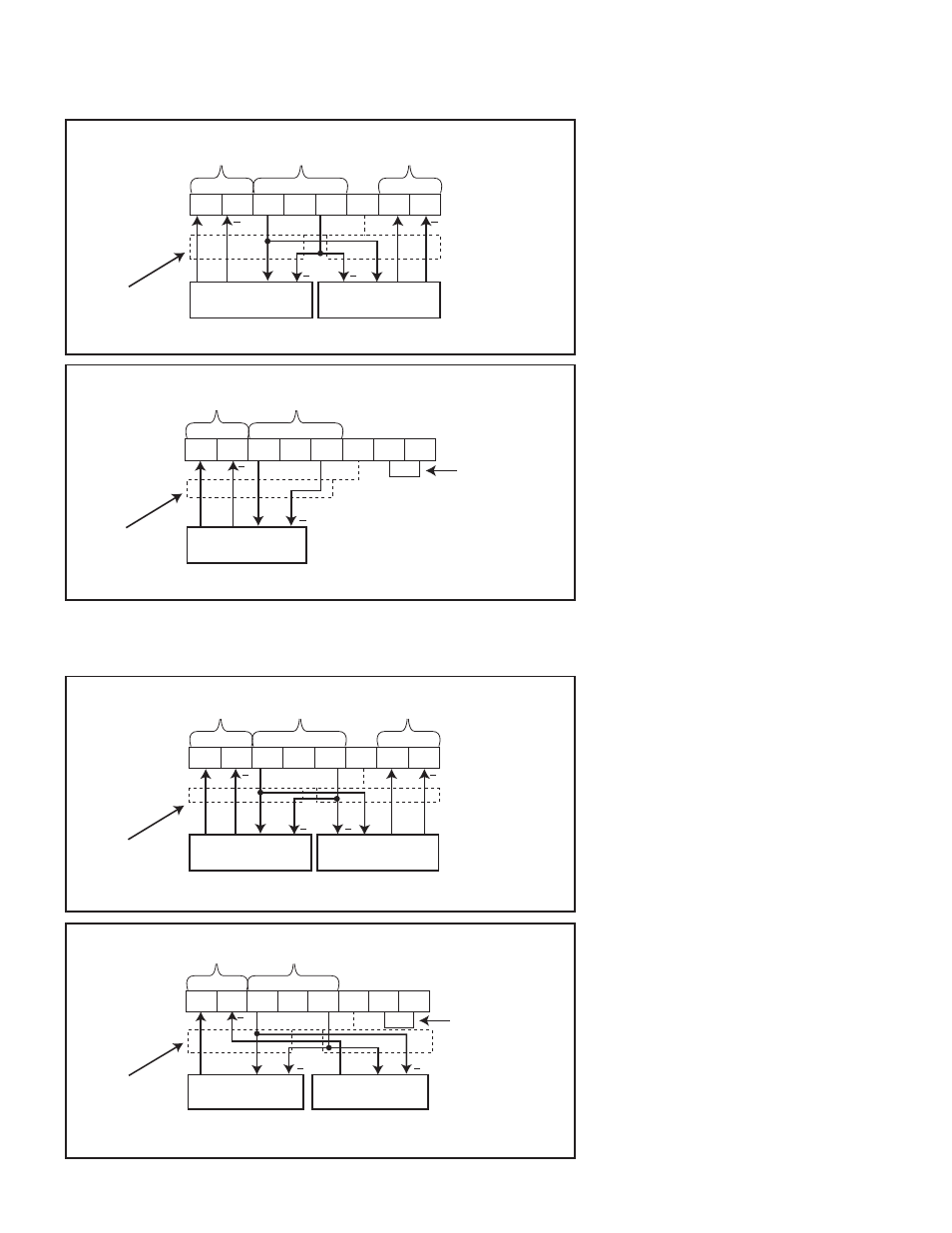
GENERIC SENSOR CONNECTION DIAGRAMS
S
INGLE
-E
NDED
O
UTPUT
S
ENSORS
Figure 12
Dual Sensor Wiring
Figure 13
Single Sensor Wiring
D
IFFERENTIAL
O
UTPUT
S
ENSORS
Figure 14
Full Bridge Sensor Wiring
Figure 15
Half Bridge Sensor Wiring
Excitation
Voltage
Add jumper wire
Channel 1
Input
No. 1 Sensor
No. 2 Sensor
Shield
Excitation
Voltage
Channel 2
Input
No. 1 Sensor
No. 2 Sensor
Shield
Excitation
Voltage
Channel 2
Input
Channel 1
Input
No. 1 Sensor
No. 2 Sensor
Shield
Channel 1
Input
Excitation
Voltage
No. 1 Sensor
Shield
Add jumper wire
NOTE: Figures 12, 13, 14 & 15
assume a normal implementation
where an increase in sensor
measurement corresponds to
an increase in voltage. For
implementations where an increase
in sensor measurement corresponds
to a decrease in output voltage, the
sensor signal wires must be inverted.
An increase in sensor measurement
must correspond to an increase in
sensor voltage.
*See Note.
*See Note.
*See Note.
*See Note.
- RPS20 966611 (18 pages)
- RPS20 966753 (1 page)
- RB15B 968179 (9 pages)
- RBR25 960613 (9 pages)
- RLSSB 150-063-C-A 966304 (10 pages)
- SBPA02 964621 (13 pages)
- SBP02 964610 (14 pages)
- SBP04 964828 (2 pages)
- SBP07 965008 (14 pages)
- BSB02 964640 (13 pages)
- HG17 969000 (7 pages)
- HGP17 969011 (16 pages)
- RPS4014G-B0192T/023-EP2U 966725 (10 pages)
- RPS20G-C0140T/072-EP2U 966705 (17 pages)
- RPS25G-B,C0064T-EP1 966950 (13 pages)
- PRD1500 966903 (2 pages)
- PRD400 966904 (10 pages)
- I300 965500 (9 pages)
- MTL300-ECC-SP-32MM-20MM-150/240 976131-225 (8 pages)
- MDU-625 928600 (21 pages)
- MDO-1375 936400 (24 pages)
- Micro 856802 (9 pages)
- B-275 802871 (12 pages)
- F-450 802850 (14 pages)
- BWB 846800 (11 pages)
- XHW 810905 (10 pages)
- FMCE-625 801487 (19 pages)
- FMCE-130-19 801673 (14 pages)
- 5H50PSP-E 913044 (15 pages)
- 5H20P-E 911319 (13 pages)
- 5H50PSP 912509 (15 pages)
- 5H50P 910305 (23 pages)
- 5H30P-E 913008 (1 page)
- 5H100PSE-E 913123 (4 pages)
- 5H60P-E 913058 (14 pages)
- 5H40S 911320 (13 pages)
- 5H60PSP-SE 910440 (19 pages)
- LSCC-54 923578 (12 pages)
- 3-Way Valve 948809 (3 pages)
- TL80 911785 (10 pages)
- 4H70P 921700 (15 pages)
- DPB 15T 963900 (16 pages)
- DPB-15T 963002 (13 pages)
- DPB 11T 961900 (15 pages)
- QFE-2500 964097 (22 pages)