Sc100, Electrical connections – Nexen SC100 964420 User Manual
Page 6
FORM NO. L-21163-C-0808
6
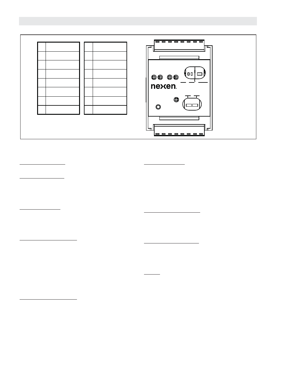
ELECTRICAL CONNECTIONS
+24 VDC & Common: The SC100 requires 24 VDC to
operate (Refer to SPECIFICATIONS for current rating).
Isolated +VDC Input: In cases where isolated Control
Outputs are desired, this input is the supply line for the
isolated 15-24 VDC power supply (supplied by user). If
isolation is not needed, this input must be connected to
the +24 VDC input.
Isolated Common: In cases where isolated Control
Outputs are desired, this input is the return line for the
isolated power supply (supplied by user). If isolation is
not needed, this input must be connected to the DC
Common input.
Out 1 and Out 1 Common: This is the control output
and return line for Channel 1. This output signal can
be used as an input to a PLC, PC, indicator or other
controls. The output can be confi gured to be the output
for Sensor 1 or the summation of Sensor 1 and Sensor
2. This function is chosen by the Out Mode switch
(Refer to Switch Settings). The output can also be set to
0-10 VDC or 4-20 mA, chosen with the CH1 Out switch
(Refer to Switch Settings). Both ranges are factory
calibrated and ready for use.
Out 2 and Out 2 Common: This is the control output
and return line for Channel 2. This output signal can
be used as an input to a PLC, PC, indicator or other
controls. This output refers to Sensor 2. This output can
be set to 0-10 VDC or 4-20 mA, chosen with the CH2
Out switch (Refer to Switch Settings). Both ranges are
factory calibrated and ready for use.
Excitation Voltage: The excitation voltage is made up
of three lines: +Vex, -Vex and Common. These three can
be used in any combination to fi t the specifi c sensor
specifi cation. For bipolar excitation voltage, use +Vex
and -Vex. For unipolar excitation voltage, use +Vex and
Common. The excitation voltage is adjustable from 5 to
15 VDC by adjusting Vex located on the cover of the
unit (Refer to SETUP).
+Sensor 1 and -Sensor 1: This is the input for sensor
1, which accepts both differential and single-ended inputs.
The input voltage range is 0-500 mV for summed
outputs and 0-1 V for individual outputs (Refer to
SPECIFICATIONS).
+Sensor 2 and -Sensor 2: This is the input for sensor
2, which accepts both differential and single-ended
inputs. The input voltage range is 0-500 mV for summed
outputs and 0-1 V for individual outputs (Refer to
SPECIFICATIONS).
Shield: This is a ground connection for the shielding on
sensor cables. Shield all sensor wiring and keep away
from wires carrying heavy loads or AC supply power.
Figure 3
SC100
9
10
11
12
13
14
15
16
8
7
6
5
4
3
2
1
Z1
S1
Z2
S2
IND
LO
LO
SUM
OUT
MODE
HI
CH1
GAIN
HI
CH2
GAIN
CH2
OUT
CH1
OUT
PWR
VEX
V
V
1
+ 24 VDC
9
+ Sensor 1
2
DC Com
10
- Sensor 1
3 Isolated +VDC
11
+ Vex
4
Isolated Com
12
- Vex
5
Out 1
13
Com
6
Com 1
14
Shield
7
Out 2
15
+ Sensor 2
8
Com 2
16
- Sensor 2