Setup – Nexen SC100 964420 User Manual
Page 11
11
FORM NO. L-21163-C-0808
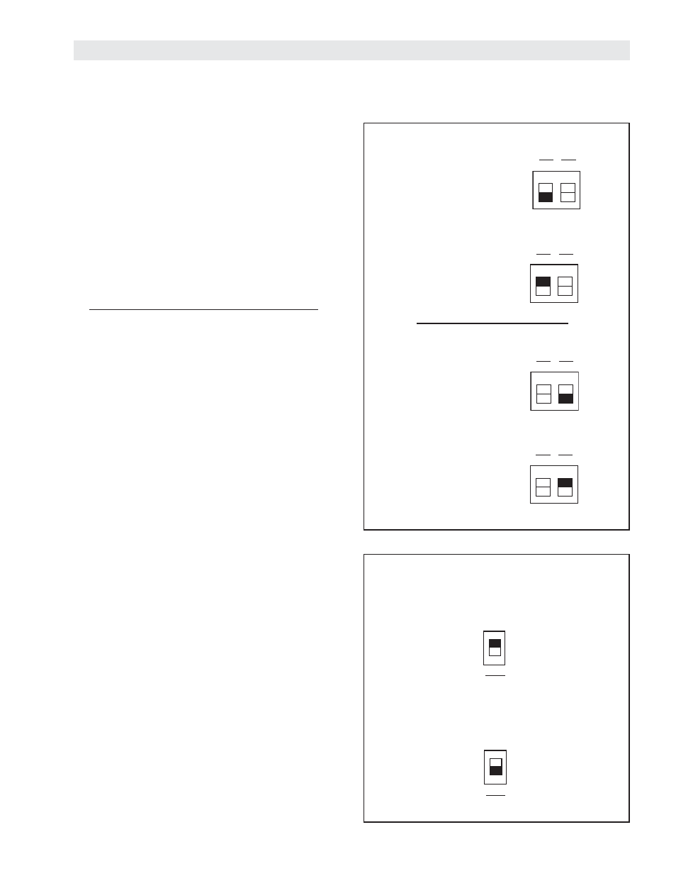
Set for Individual or Summed outputs.
Individual Outputs:
Output 1 = Channel 1
Output 2 = Channel 2
Summed output:
Output 1 = Channel 1 + Channel 2
Output 2 = Channel 2
SETUP
SWITCH SETTINGS
Figure 16
V
OLTAGE
OR
C
URRENT
O
UTPUT
S
ELECTOR
Both output channels are equipped with voltage or
current outputs. This is user selectable via CH1 OUT
and CH2 OUT switches accessed through the cover of
the SC100.
Setting output channels:
Using a screw driver or your fi nger, slide the switch to
‘I’ for 4-20 mA output or to ‘V” for 0-10 V output. (See
Figure 16).
Figure 17
O
UTPUT
M
ODE
The SC100 outputs can be set with both sensor
channels summed together or each sensor channel
separately.
Individual Outputs:
Channel 1 output is an amplifi cation of Channel
1 sensor input. Similarly, channel 2 output is an
amplifi cation of the channel 2 sensor input.
Individual Outputs are generally used for web guide
sensors, different sensor types using the same SC100,
or load cells measuring tension in different tension
zones.
Summed Output:
Channel 1 output is the summation of the amplifi cation
of Channel 1 and Channel 2 sensor inputs. Channel 2
output is the amplifi cation of channel 2 sensor input.
Summed Output is generally used for a pair of load cells
or strain gauges measuring tension in a single tension
zone (See Figure 17).
2
1
2
1
2
1
CH1
Out
I
CH2
Out
I
V
V
IND
SUM
OUT
MODE
NOTE: When using the summed output, each channel
must be calibrated separately. This means when a total
maximum output of 10 V is needed, each channel must
be spanned to 5 V.
2
1
IND
Voltage Output
Channel 1 Output
Current Output
Channel 2 Output
Voltage Output
Current Output
CH1
Out
I
CH2
Out
I
V
V
CH1
Out
I
CH2
Out
I
V
V
CH1
Out
I
CH2
Out
I
V
V
SUM
OUT
MODE