Nexen SC100 964420 User Manual
Page 13
13
FORM NO. L-21163-C-0808
CALIBRATION
NOTE: Prior to calibration, make sure the Span and Zero Potentiometers are fully counterclockwise and the Output
Selector switches are set to Individual and voltage output for both Channel 1 and Channel 2.
This procedure refers to the 0–10 VDC output, however the 4-20 mA will also change automatically in proportion
to the voltage output.
When calibration procedure is complete, place the Output selector switches to the setting required for the
application, Refer to SWITCH SETTINGS.
TENSION SENSORS
Z
ERO
A
DJUSTMENT
1. Apply Power to the SC100.
2. Unload the sensor or sensors making sure their
outputs represent the minimum value or at rest
condition.
3. Connect a voltmeter to terminals 5 (+) and 6 (-).
4. Rotate Z1 until the voltmeter reads 0.025 VDC.
5. Connect a voltmeter to terminals 7 (+) and 8 (-).
6. Rotate Z2 until the voltmeter reads 0.025 VDC.
S
PAN
A
DJUSTMENT
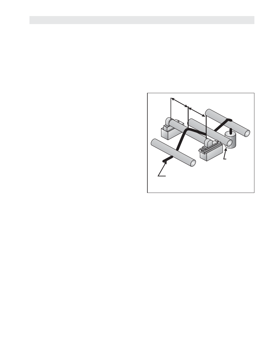
1. Apply a known load to the sensor 1 (See Figure 19).
2. Connect a voltmeter to terminals 5 (+) and 6 (-).
3. Rotate S1 clockwise to increase the reading to the
desired voltage level. Example: Maximum Load =
100 lbs, with a 50 lb known load adjust the output
for 5.0 VDC to achieve a 10V output at maximum
load.
NOTE: If using one sensor, skip steps 4 through 6.
4. Connect a voltmeter to terminals 7 (+) and 8 (-).
5. Rotate S2 clockwise to increase the reading to the
desired voltage level.
6. Repeat
the
Zero Adjustment and Span Adjustment
procedures detailed above.
NOTE: Span Adjustments procedures may offset
the Zero Adjustment settings. Repeating both
procedures will ensure that settings are accurate.
7. Set the Output Mode switch to the desired setting,
either Individual or Summed (See Switch Settings in
SETUP section).
Figure 19
Thread rope through the
center and secure this end.
Hang a known
weight from
this end.