Parts replacement - friction facing (all models) – Nexen OPS-625 801692 User Manual
Page 9
9
FORM NO. L-20318-E-1112
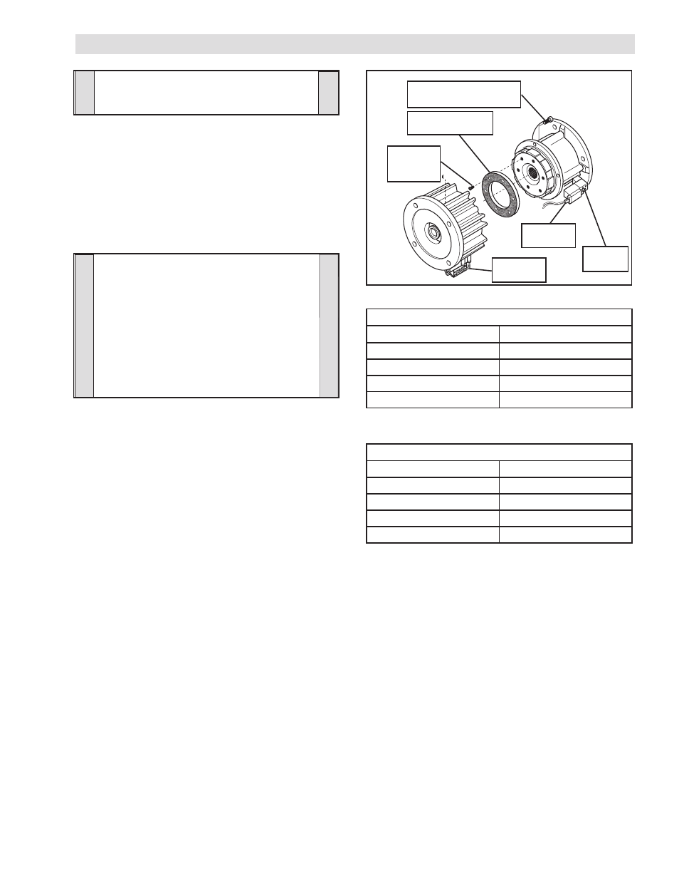
1. Disconnect the Red and Black leads from the Connector
(Item 30), located on the Solenoid Valve, from Terminals 5
and 6 of the Connector (Item 33) by pushing a screwdriver
into the slot on the top of the Connector; then, pull the two
leads from the Solenoid Valve out of the Connector (See
Figure 9).
2. Remove the four Socket Head Cap Screws (Item 12) and
separate the two halves of the FMCE (See Figure 9).
TABLE 4
TABLE 3
FIGURE 9
Socket Head Cap Screw
(Item 12)
Friction Facing
(Item 8)
Solenoid
Valve
Connector
(Item 33)
Flat Head
Screw
(Item 7)
Connector
(Item 30)
PARTS REPLACEMENT - FRICTION FACING (ALL MODELS)
NOTE
The Flat Head Screws are installed with an
anaerobic locking compound. Inserting a
properly fitting screwdriver into the head
of the Flat Head Screw and striking the
screwdriver with a hammer will break the
crystalline structure of this locking compound
and allow removal of the Flat Head Screws.
Never use an impact wrench to remove the
Flat Head Screws.
3. Remove the six old Flat Head Screws (Item 7) and the old
Friction Facing (Item 8) (See Figure 9).
4. Install the new Friction Facing (Item 8) and new Flat Head
Screws (Item 7) (See Figure 9).
5. Tighten the six new Flat Head Screws to the recommended
torque (See Table 3).
6. Apply a drop of Loctite
242 to the threads of the Socket
Head Cap Screws (Item 12) (See Figure 9).
7. Reinstall and tighten the four Socket Head Cap Screws
(Item 12) to the recommended torque (See Table 4).
8. Reconnect the Red and Black leads from the Connector
(Item 30), located on the Solenoid Valve, to Terminals 5
and 6 of the Connector (Item 33) by pushing a screwdriver
into the slot on the top of the Connector; then, push the
two leads from the Solenoid Valve into the Connector (See
ELECTRICAL CONNECTIONS).
RECOMMENDED TIGHTENING TORQUE (Item 7)
MODEL
TIGHTENING TORQUE
FMCE 625
22 In. Lbs. [2.5 N•m]
FMCE 875
22 In. Lbs. [2.5 N•m]
FMCE 1125
71 In. Lbs. [8.0 N•m]
FMCE 1375
71 In. Lbs. [8.0 N•m]
RECOMMENDED TIGHTENING TORQUE (Item 12)
MODEL
TIGHTENING TORQUE
FMCE 625
157 In. Lbs. [17.7 N•m]
FMCE 875
267 In. Lbs. [30.2 N•m]
FMCE 1125
267 In. Lbs. [30.2 N•m]
FMCE 1375
594 In. Lbs. [55.5 N•m]
CAUTION
Use caution not to bump or damage the
Sensors during assembly or disassembly.