Nexen OPS-625 801692 User Manual
Page 5
5
FORM NO. L-20318-E-1112
1. Insert the Key (Item 25) into the output shaft of the FMCE
(See Figure 4).
2. Slide the FMCE output shaft into the gear reducer (See
Figure 4).
3. Secure the FMCE to the gear reducer using customer
supplied socket head cap screws, lock washers, and nuts
(See Figure 4).
4. Insert the customer supplied key into the motor shaft keyway
(See Figure 4).
5. Remove the Socket Head Cap Screws (Item 24) and the
Female Pilot (Item 13); then, secure the Female Pilot to the
motor face using customer supplied socket head cap screws
(See Figure 4).
6. Slide the FMCE Housing (Item 1) onto the motor shaft (See
Figure 4).
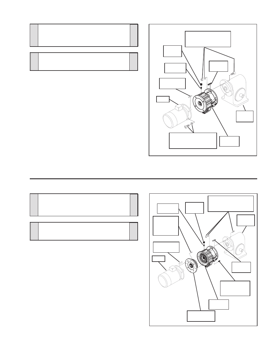
FMCE 625 MOUNTED BETWEEN A GEAR REDUCER AND A MOTOR
FMCE 875, 1125, AND 1375 MOUNTED BETWEEN A GEAR REDUCER AND A MOTOR
1. Insert the Key (Item 25) into the output shaft of the FMCE
(See Figure 3).
2. Slide the FMCE output shaft into the gear reducer (See
Figure 3).
3. Secure the FMCE to the gear reducer using customer
supplied socket head cap screws, lock washers, and nuts
(See Figure 3).
4. Insert the customer supplied key into the motor shaft keyway
(See Figure 3).
5. Slide the motor into the FMCE and secure it to the FMCE
using customer supplied socket head cap screws and lock
washers (See Figure 3).
6. Align the Set Screw (Item 26) in the Drive Disc (Item 4) with
the hole in the FMCE Housing (See Figure 3).
7. Tighten the Set Screw (Item 26); then, install the Plug (Item
27) (See Figure 3).
Motor
FMCE
Housing
Customer
supplied key
Gear
Reducer
Key
(Item 25)
Customer supplied
socket head cap screws,
lock washers, and nuts
Plug
(Item 27)
Set Screw
(Item 26)
Customer supplied
socket head cap screws
and lock washers
FIGURE 3
Customer
supplied key
Motor
FMCE
Housing
Gear
Reducer
Key
(Item 25)
Customer supplied
socket head cap screws,
lock washers, and nuts
Set Screw
(Item 26)
Customer
supplied
socket head
cap screws
FIGURE 4
Socket Head
Cap Screws
(Item 12 or 24)
Plug
(Item 27)
Female Pilot
(Item 13)
CAUTION
Use caution not to bump or damage the
Sensors during assembly or disassembly.
NOTE
Align the Solenoid Valve, located on the
FMCE, to a down position to allow condensa-
tion to drain out of the air chamber
CAUTION
Use caution not to bump or damage the
Sensors during assembly or disassembly.
NOTE
Align the Solenoid Valve, located on the
FMCE, to a down position to allow condensa-
tion to drain out of the air chamber