Electrical connections – Nexen OPS-625 801692 User Manual
Page 7
7
FORM NO. L-20318-E-1112
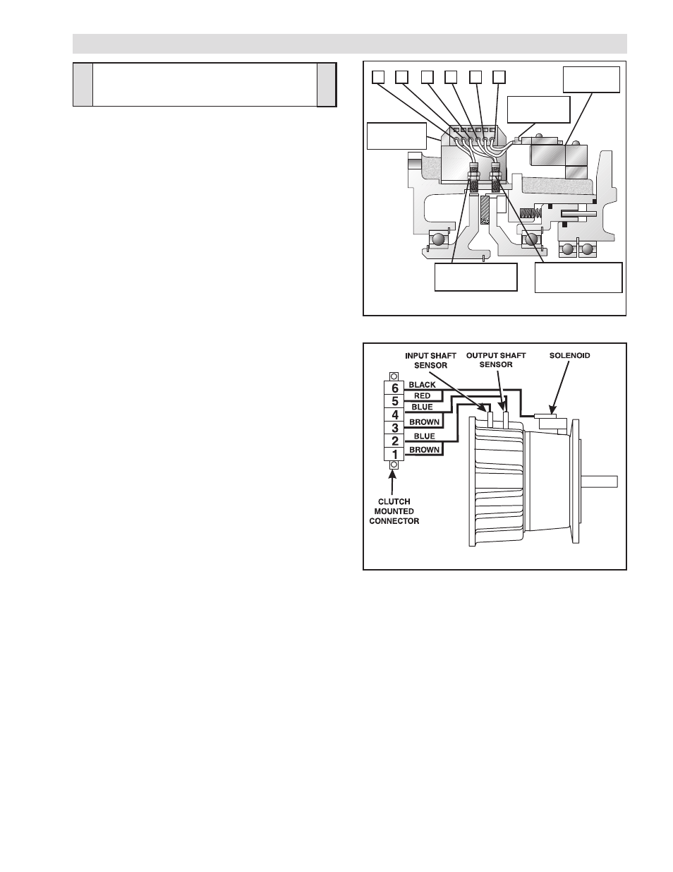
1. Connect the Red and Black leads from the Connector (Item
30), located on the Solenoid Valve, to Terminals 5 and 6 of
the Connector (Item 33) by pushing a screwdriver into the
slot on the top of the Connector and then inserting the Red
and Black leads (See Figures 6 and 7).
2. Connect the Brown and Blue leads from the Input Sensor
(Item 31) to Terminals 1 and 2 of the Connector (Item 33)
by pushing a screwdriver into the slot on the top of the
Connector and then inserting the Brown and Blue leads
(See Figures 6 and 7).
3. Connect the Brown and Blue leads from the Output Sensor
(Item 31) to Terminals 3 and 4 of the Connector (Item 33)
by pushing a screwdriver into the slot on the top of the
Connector and then inserting the Brown and Blue leads
(See Figures 6 and 7).
FIGURE 7
1 2 3 4 5 6
Solenoid
Valve
Input Sensor
(Item 31)
Output Sensor
(Item 31)
Connector
(Item 30)
FIGURE 6
Connector
(Item 33)
ELECTRICAL CONNECTIONS
CAUTION
Use caution not to bump or damage the
Sensors during assembly or disassembly.