Nexen OPS-625 801692 User Manual
Page 13
13
FORM NO. L-20318-E-1112
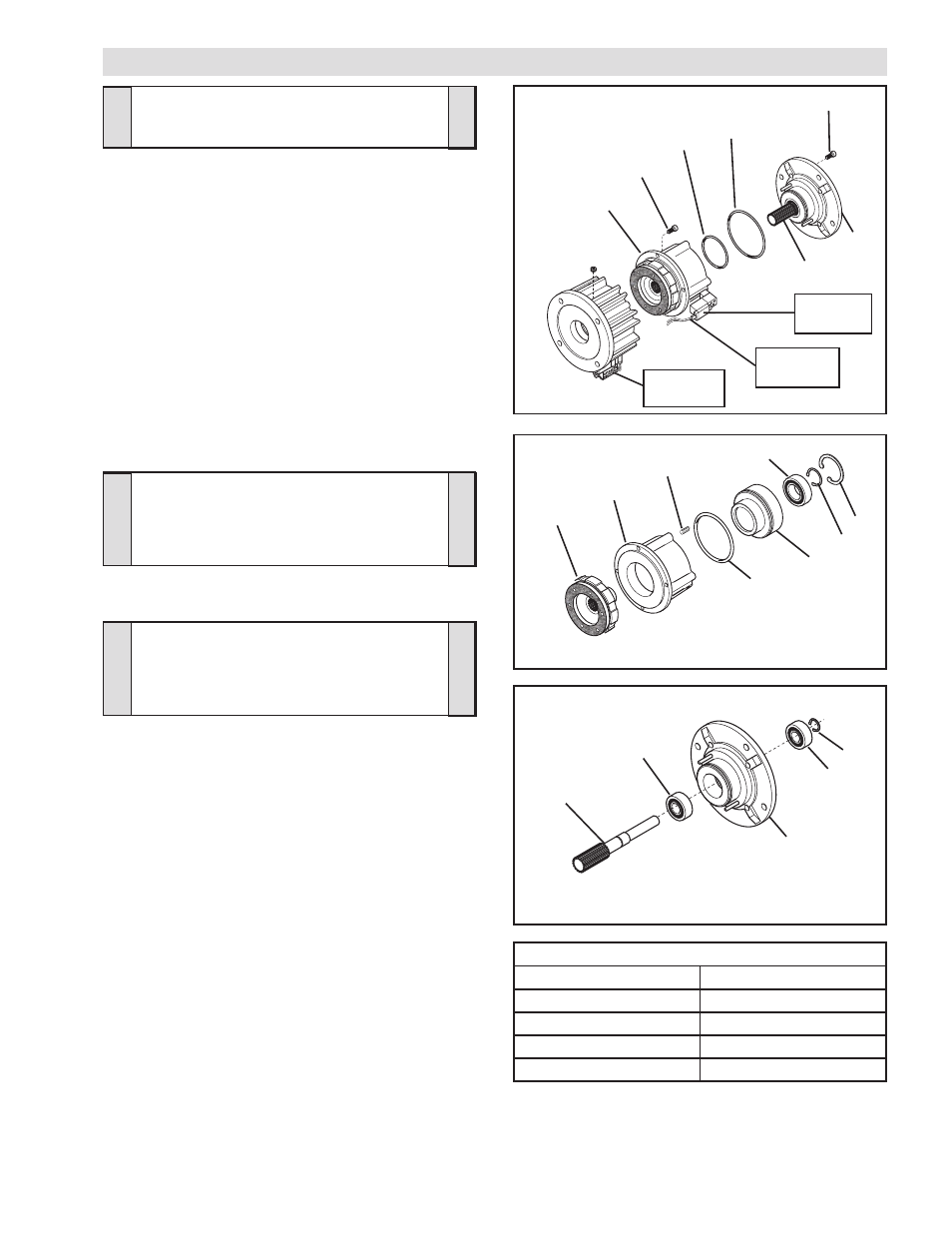
FIGURE 15
3
6
2
15
14
10
11
9
FIGURE 16
23
18
18
22
19
TABLE 7
Solenoid
Valve
22
19
12
21
20
12
Connector
(Item 33)
FIGURE 14
Connector
(Item 30)
11
PARTS REPLACEMENT - BEARINGS AND O-RING SEALS (ALL MODELS)
WARNING
Special attention should be exercised when
working with retaining rings. Always wear
safety goggles when working with spring or
tension loaded fasteners or devices.
CAUTION
Use caution not to bump or damage the
Sensors during assembly or disassembly.
WARNING
The Piston (Item 15) is spring loaded. Always
wear safety goggles when working with
spring or tension loaded fasteners or devices.
1. Disconnect the Red and Black leads from the Connector
(Item 30), located on the Solenoid Valve, from Terminals 5
and 6 of the Connector (Item 33) by pushing a screwdriver
into the slot on the top of the Connector; then, pull the two
leads from the Solenoid Valve out of the Connector (See
Figure 14).
2. Remove the four Socket Head Cap Screws (Item 12) and
separate the two halves of the FMCE (See Figure 14).
3. Remove the four Socket Head Cap Screws (Item 12)
securing the Male Pilot (Item 19) to the Air Chamber (Item
11) (See Figure 14).
4. Remove the Male Pilot (Item 19) and Stub Shaft (Item 22)
from the Air Chamber (Item 11) (See Figure 14).
5. Remove and discard the old O-ring Seals (Items 20 and 21)
(See Figure 14).
6. Using a "C" clamp, compress the Piston (Item 15) into the
Air Chamber (Item 11) (See Figure 15).
7. Remove the Retaining Ring (Item 6) from the Splined Disc
(Item 9) (See Figure 15).
8. Press the Splined Disc (Item 9) from the Bearing (Item 2)
(See Figure 15).
9. Slowly release the "C" clamp holding the Piston (Item 15)
in the Air Chamber (Item 11); then, remove the Piston (Item
15) from the Air Chamber (Item 11) (See Figure 15).
10. Remove the six Compression Springs (Item 10) (See Figure
15).
11. Remove the Retaining Ring (Item 3) from the Piston (Item
15) (See Figure 15).
12. Remove and discard the old O-ring Seal (Item 14) from the
Piston (Item 15) (See Figure 15).
13. Press the Bearing (Item 2) out of the Piston (Item 15) (See
Figure 15).
14. Clean the bearing bore of the Piston with fresh safety solvent,
making sure all old Loctite
®
residue is removed.
RECOMMENDED TIGHTENING TORQUE (Item 12)
MODEL
TIGHTENING TORQUE
FMCE 625
157 In. Lbs. [17.7 N•m]
FMCE 875
267 In. Lbs. [30.2 N•m]
FMCE 1125
267 In. Lbs. [30.2 N•m]
FMCE 1375
594 In. Lbs. [55.5 N•m]