Nexen OPS-625 801692 User Manual
Page 11
11
FORM NO. L-20318-E-1112
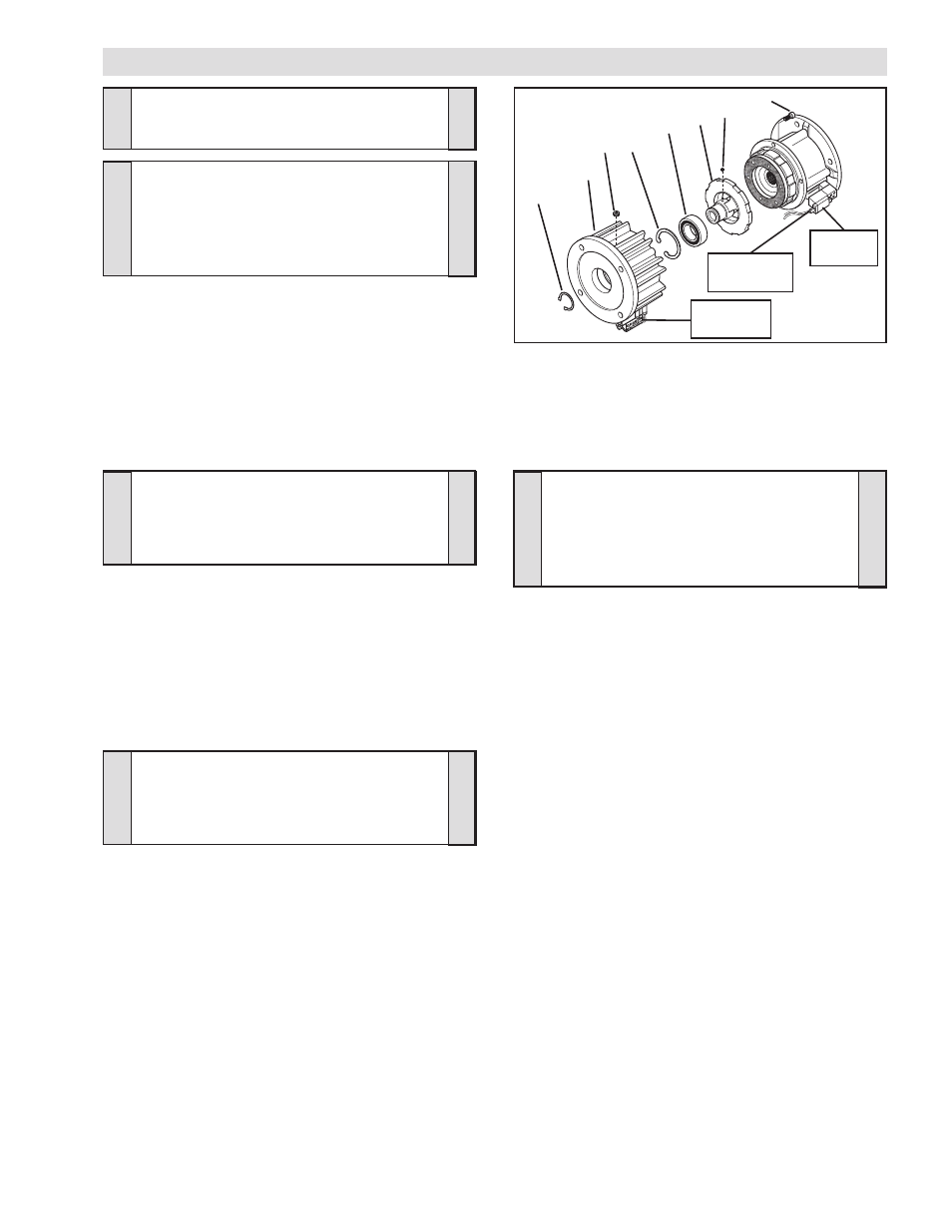
1. Disconnect the Red and Black leads from the Connector
(Item 30), located on the Solenoid Valve, from Terminals 5
and 6 of the Connector (Item 33) by pushing a screwdriver
into the slot on the top of the Connector; then, pull the two
leads from the Solenoid Valve out of the Connector (See
Figure 12).
2. Remove the four Socket Head Cap Screws (Item 12) and
separate the two halves of the FMCE (See Figure 12).
3. Remove the Retaining Ring (Item 6) (See Figure 12).
4. Press the Drive Disc (Item 4) out of the Bearing (Item 2) and
the Housing (Item 1) (See Figure 12).
5. Remove the Retaining Ring (Item 3) (See Figure 12).
6. Fully supporting the Housing (Item 1), press the old Bearing
(Item 2) out of the Housing (Item 1) (See Figure 12).
7. Clean the bearing bore of the Housing (Item 1) with fresh
6
1
4
2
3
12
Solenoid
Valve
FIGURE 12
Connector
(Item 33)
27
26
Connector
(Item 30)
PARTS REPLACEMENT - HOUSING BEARING, MODEL FMCE 625
NOTE
If an Input Unit is installed on the FMCE, it
must be removed before servicing the FMCE.
Remove the Plug (Item 27) and loosen the Set
Screw (Item 26) to release the FMCE from the
Input Unit (See Figure 12).
CAUTION
Use caution not to bump or damage the
Sensors during assembly or disassembly.
WARNING
Special attention should be exercised when
working with retaining rings. Always wear
safety goggles when working with spring or
tension loaded fasteners or devices.
NOTE
Do not reuse the bearing. Applying force to
the inner bearing race to remove a bearing
held by the outer race causes damage to
the bearing.
safety solvent, making sure all old Loctite
®
residue is
removed (See Figure 10).
8. Apply an adequate amount of Loctite
®
680 to evenly coat
the outer race of the new Bearing (Item 2) (See Figure 12).
9. Carefully align the outer race of the new Bearing (Item 2)
with the bore of the Housing (Item 1) (See Figure 12).
10. Supporting the Housing (Item 1) and pressing on the outer
race of the new Bearing (Item 2), press the new Bearing
into the Housing (See Figure 12).
11. Reinstall the Retaining Ring (Item 3) (See Figure 12).
12. Support the inner race of the new Bearing (Item 2) and press
the Drive Disc (Item 4) into the new Bearing and Housing
(Item 1) (See Figure 12).
13. Reinstall the Retaining Ring (Item 6) (See Figure 12).
14. Apply a drop of Loctite
®
242 to the threads of the Socket
Head Cap Screws (Item 12) (See Figure 12).
NOTE
If you are replacing all the Bearings and
O-ring Seals in the FMCE, proceed to PARTS
REPLACEMENT–BEARINGS AND O-RING
SEALS; otherwise, proceed with the next step.
15. Slide the Housing (Item 1), Bearing (Item 2), and Drive Disc
(Item 4) into the FMCE and reinstall the four Socket Head
Cap Screws (Item 12) (See Figure 12).
16. Tighten the four Socket Head Cap Screws (Item 12) to 157
In. Lbs. [17.7 N•m] torque.
17. Reconnect the Red and Black leads from the Connector
(Item 30), located on the Solenoid Valve, to Terminals 5
and 6 of the Connector (Item 33) by pushing a screwdriver
into the slot on the top of the Connector; then, push the
two leads from the Solenoid Valve into the Connector (See
ELECTRICAL CONNECTIONS).