Parts replacement - sensors (all models) – Nexen OPS-625 801692 User Manual
Page 10
10
FORM NO. L-20318-E-1112
FIGURE 11
0.03 In.
[0.8 mm]
gap between
Sensor and
high spot on
Drive Disc
New Output
Sensor
(Item 31)
Connector
(Item 33)
New Input
Sensor
(Item 31)
Drive Disc
(Item 4)
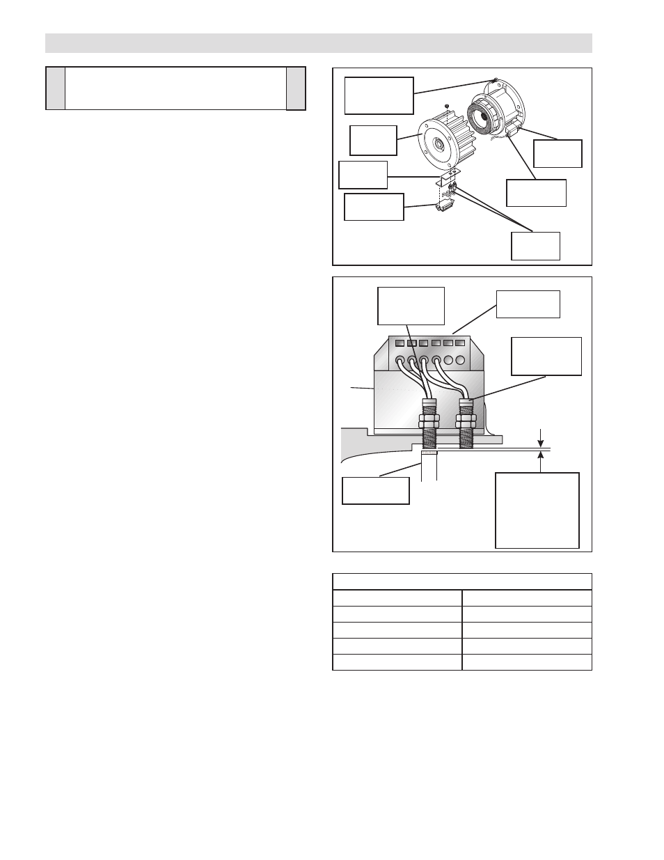
1. Disconnect the Red and Black leads from the Connector
(Item 30), located on the Solenoid Valve, from Terminals 5
and 6 of the Connector (Item 33) by pushing a screwdriver
into the slot on the top of the Connector; then, pull the two
leads from the Solenoid Valve out of the Connector (See
Figure 10).
2. Remove the four Socket Head Cap Screws (Item 12) and
separate the two halves of the FMCE (See Figure 10).
3. Disconnect the Brown and Blue leads from each of the
Sensors (Item 31) from Terminals 1, 2, 3, and 4 of the
Connector (Item 33) by pushing a screwdriver into the slot
on the top of the Connector; then, pull the two leads from
the Sensors out of the Connector.
4. Remove the two old Input and Output Sensors (Item 31)
from the Housing (Item 1) (See Figure 10).
5. Install the first new Input Sensor (Item 31) into the Housing
(Item 1) directly over a high spot on the Drive Disc (Item 4)
(See Figure 11).
6. Adjust the first new Input Sensor probe until it is
approximately 0.03149 In. [0.8 mm] from the high spot on
the Drive Disc (Item 4) and lock the new Input Sensor in
place (See Figure 11).
7. Install the new Output Sensor (Item 31) into the Housing
(Item 1) until it is exactly flush with the probe of the installed
Input Sensor and lock the Output Sensor in place (See
Figure 11).
8. Apply a drop of Loctite
242 to the threads of the Socket
Head Cap Screws (Item 12).
9. Reinstall and tighten the four Socket Head Cap Screws
(Item 12) to the recommended torque (See Table 5).
10. Reconnect the Brown and Blue leads from the Sensors
(Item 31) to Terminals 1, 2, 3, and 4 of the Connector (Item
33) (See ELECTRICAL CONNECTIONS).
11. Reconnect the Red and Black leads from the Connector
(Item 30), located on the Solenoid Valve, to Terminals 5 and
6 of the Connector (Item 33) by pushing a screwdriver into
the slot on the top of the Connector (Item 33); then, push
the two leads from the Solenoid Valve into the Connector
(See ELECTRICAL CONNECTIONS).
TABLE 5
Solenoid
Valve
FIGURE 10
Socket Head
Cap Screws
(Item 12)
Housing
(Item 1)
Connector
(Item 33)
Sensors
(Item 31)
B r a c k e t
(Item 32)
Connector
(Item 30)
PARTS REPLACEMENT - SENSORS (ALL MODELS)
RECOMMENDED TIGHTENING TORQUE (Item 12)
MODEL
TIGHTENING TORQUE
FMCE 625
157 In. Lbs. [17.7 N•m]
FMCE 875
267 In. Lbs. [30.2 N•m]
FMCE 1125
267 In. Lbs. [30.2 N•m]
FMCE 1375
594 In. Lbs. [55.5 N•m]
CAUTION
Use caution not to bump or damage the
Sensors during assembly or disassembly.