Air connections lubrication, Lubricator drip rate settings – Nexen OPS-625 801692 User Manual
Page 6
6
FORM NO. L-20318-E-1112
7. Apply a drop of Loctite
®
242 to the threads of the Socket
Head Cap Screws (Item 24) (See Figure 4).
8. Secure the FMCE Housing (Item 1) to the Female Pilot
(Item 13) using Socket Head Caps Screws (Item 24); then,
alternately and evenly tighten the Socket Head Cap Screws
to the recommended torque (See Figure 4 and Table 2).
9. Align the Set Screw (Item 26) in the Drive Disc (Item 4) with
the hole in the FMCE Housing (See Figure 4).
10. Tighten the Set Screw (Item 26); then, install the Plug (Item
27) (See Figure 4).
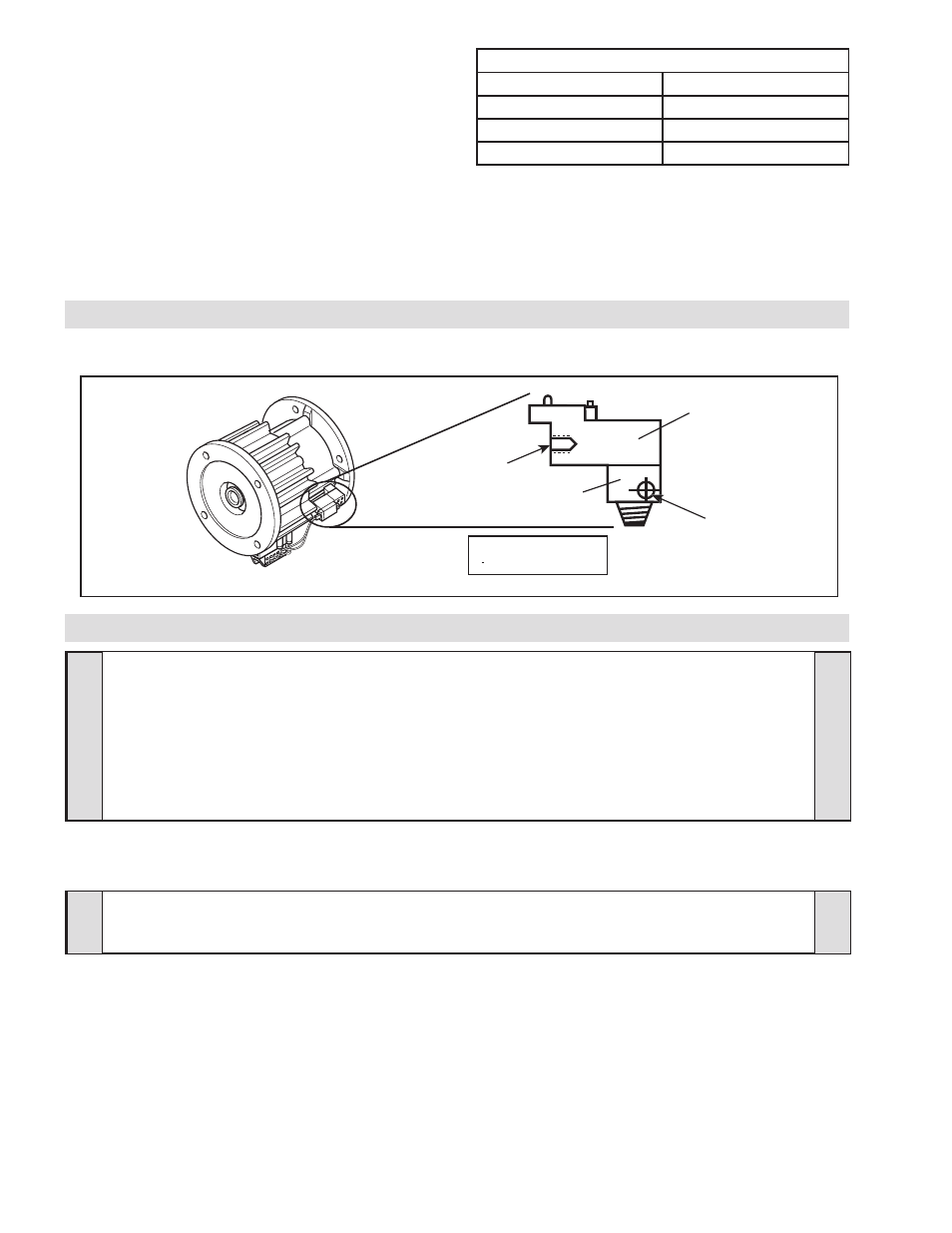
1. Connect the air line to the air inlet port of the Solenoid Valve
(See Figure 5).
AIR CONNECTIONS
LUBRICATION
TABLE 2
RECOMMENDED TIGHTENING TORQUE
MODEL
TIGHTENING TORQUE
FMCE 875 (Item 24)
157 In. Lbs. [17.7 N•m]
FMCE 1125 (Item 24)
267 In. Lbs. [30.2 N•m]
FMCE 1375 (Item 24)
580 In. Lbs. [65.0 N•m]
1. Close and disconnect the air line from the unit.
2. Turn the Lubricator Adjustment Knob clockwise three com-
plete turns.
3. Open the air line.
4. Close the air line to the unit when a drop of oil forms in the
Lubricator Sight Gage.
5. Connect the air line to the unit.
6. Turn the Lubricator Adjustment Knob counterclockwise until
closed.
7. Turn the Lubricator Adjustment Knob clockwise one-third
turn.
8. Open the air line to the unit.
LUBRICATOR DRIP RATE SETTINGS
NOTE
Pneumatically actuated devices require clean, pressure regulated, and lubricated air for maximum performance
and long life. The most effective and economical way to lubricate the FMCE is with an Air Line Lubricator,
which injects oil into the pressurized air, forcing an oil mist into the air chamber.
Locate the lubricator above and within ten feet of the FMCE, and use a low viscosity oil such as SAE-10.
Synthetic lubricants are not recommended.
NOTE
These settings are for Nexen supplied lubricators. If you are not using a Nexen lubricator, calibration must
replicate the following procedure.
FIGURE 5
Exhaust
Port
Adapter
Air Supply Port
#10-32
for N.C. Operation
Valve
Normally Closed
3 Way Solenoid Valve