Caution, Warning – Nexen VC500 837450 User Manual
Page 8
8
FORM NO. L-21156-F-0209
WARNING
CAUTION
aIr COnneCTIOnS
Pneumatically actuated devices require clean, pressure
regulated, and lubricated air for maximum performance
and long life. Your Nexen distributor carries filters,
regulators, and lubricators specifically designed to
operate with Nexen clutches, brakes, and valves.
Piping diagrams are included in this manual for a variety
of braking functions. Refer to OPERATIONAL MODES
for details.
Do not use rigid pipe or tubing when
connecting directly to the brake. Prevent
unshielded air hoses from rubbing on
metal surfaces or edges, as this will
cause rapid deterioration of the hose.
actuator is spring loaded
under extreme pressure. Do
not disassemble. If actuator
malfunctions, replace or contact
nexen. The turnbuckle assembly
can be used to physically release
the spring.
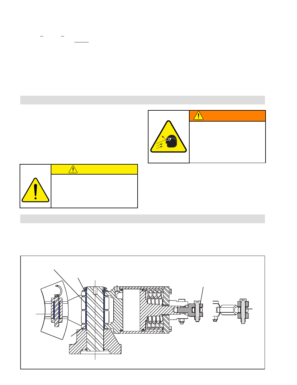
FIGure 6
lubrICaTIOn
All pivot points on the VC500 Caliper Brake use self-lubricated high PV bearings.
For tension control applications where the disc is held at elevated temperatures for extended periods, use a light
machine oil on Bearings (Items 11, 12, 13, 22, 28, and 37) (See Figure 6).
37
11
13
12
28
22
nOTe: The vC500 Caliper brake has a .250–18 nPT
air inlet port. a .250–18 nPT (male) and .250 ISO
7/1 (female) adapter is provided for metric plumbing
applications.
nOTe: DO nOT assume the thread lengths are equal
on the rod ends. use the actuator cap as a reference
to equalize linkage length (as described in step 11).
9. With >4.1 bar (>60 psi) still applied, rotate the
turnbuckles (Item 23) equally until contact is made
between the facings (Item 6) and the brake disc.
Then, back off 1/4 turn on each turnbuckle.
nOTe: The gap between the brake arm (Item 3) and
the actuator cap (Item 10) should be equal on both
sides. If not, continue to adjust turnbuckles until both
arms are equally spaced and the facings (Item 6) are
in contact with the brake disc.
10. Carefully re-tighten the jam nuts (Item 19 and 26)
to ensure that no turnbuckle movement is detected.
Apply serviceable thread lock and torque jam nuts
to 4.5 Nm (40 in-lb).
nOTe: lH jam nuts(Item 36) will have a paint mark to
identify them from the rH thread nuts.
11. Apply a serviceable thread lock to the cap screws
(Items 34) and reinstall the brake guard (Item 24).