Caution – Nexen VC500 837450 User Manual
Page 6
6
FORM NO. L-21156-F-0209
CAUTION
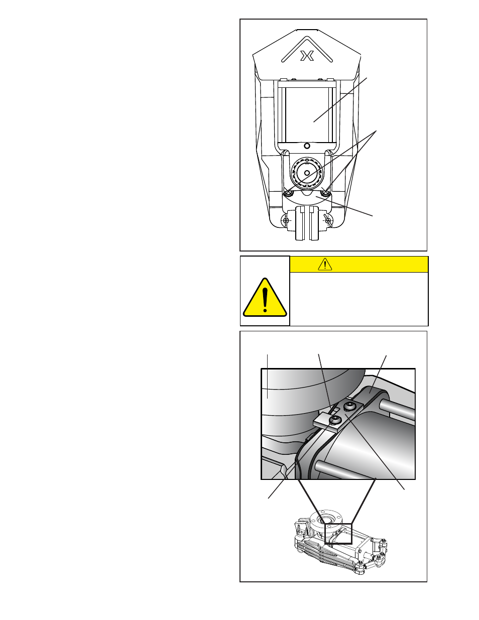
Figure 3
Frame
nOTe: The vC500 Spring actuator assembly is factory
calibrated to a 12.7 mm [0.500 in] wide brake disc. no
adjustment is necessary when mating a disc of this
size.
If using a thicker or thinner disc, offset shoes will be
required. Contact nexen for available sizes. When
replacing with offset shoes, see the FrICTIOn FaCInG
aDJuSTmenT section to readjust for a wider or thinner
disc.
1. Release the brake with at least 4.1-4.8 bar [60-70
psi] air pressure.
2. Position the brake shoes on the disc and release the
air pressure to lock the brake in place.
nOTe: brake shoes must be mounted with approximately
1.6 mm [1/16 inch] space between the outside edge of
the shoe and the outer diameter of the disc.
2. Align the frame on a support (customer supplied)
so the brake arms are parallel with the brake disc
and the brake shoes are positioned at least 1.6 mm
[1/16 inches] in from the disc edge.
nOTe: The support must be capable of sustaining loads
produced during braking.
If using shims under the Frame (Item 1): Do not to warp
the Frame when tightening the Cap Screws (customer
supplied).
V
ertical
M
ounting
o
nly
nOTe: a special bracket and Screw kit (Items 43 & 42)
is supplied with each vC500 unit to be used in vertical
mounting applications.
If mounting vertically, attach the bracket before
proceeding with step three:
Secure the bracket to the bottom of the actuator
mount (Item 4) with the supplied Screws. Position the
bracket with the notch straddling the arm of the frame
to provide support (See Figure 4). Hold the bracket
tightly to the frame, and tighten the Screws to create
a hard stop.
3. Release the VC500 from the disc.
4. Tighten the Cap Screws (customer supplied) and
the Lock Washers (Item 20) to 67.8 Nm [50 ft-lb]
torque (See Figure 3).
The Cap Screws (Item 17) must sustain the
loads produced by the mounting torque.
The torque rating specified in Tables 1 & 2
allows a significant load safety factor. DO
nOT exCeeD TOrQue lImITS SPeCIFIeD
FOr THe CaP SCreWS.
Cap Screws &
Lock Washers
(customer
supplied)
Frame
(Item 1)
Spring Actuator
Assembly
Figure 4
Frame
(Item 1)
Frame Arm
Actuator Mount
(Item 4)
Cap Screw
(Item 42)
Bracket
(Item 43)