Danger – Nexen VC500 837450 User Manual
Page 12
12
FORM NO. L-21156-F-0209
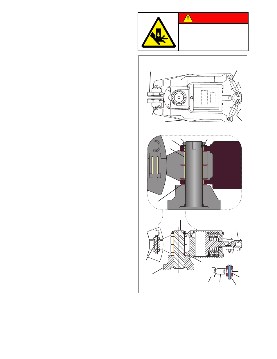
DANGER
8
Friction Facing
Shoe Assembly
(Items 5, 6, and 15)
Figure 10
bearInGS
1. Remove Brake Guard (Item 24).
2. Apply >4.1 bar (>60 psi) to open shoes or manually
release the brake (See MANUAL RELEASE
section).
3. Remove shoe pins (Item 8).
4. Remove the friction facing shoe assembly (Item 5, 6,
and 15).
5. Remove air pressure from the brake.
nOTe: nexen recommends removing the entire caliper
brake assembly from the machine at this time.
6. Open the tab (Item 35) and remove the lock nut
(Item 33).
nOTe: mark the rod ends (Item 16 & 17) and turnbuckle
assemblies (Item 23) to designate right and left side
assemblies of the brake. mark each assembly to
designate arm (Item 3) and clevis side (Item 14).
7. Remove the rod ends (Item 16 & 17) from the clevis
(Item 14) and the arm (Item 3) by removing the
locking nuts (Item 18).
nOTe: Do not adjust the rod and turnbuckle assemblies
while removed from the clevis.
8. Roll the caliper assembly on its side (or up-side-
down) and pull the pin/base (Items 1 & 2) assembly
out of the arms and actuator mount (Item 4).
9. Apply hand force to the arms (Item 3) to pry them
out of the actuator mount.
10. Collect and inspect thrust bearings (Item 12 & 20).
Replace if necessary.
11. Press the old bearings (11, 13, 22, & 37) out of the
arms (Item 3) and rod ends (Items 16 & 17).
12. Press new bearings (Items 11, 13, 22, & 37) into
the arms (Item 3) and rod ends (Items 16 & 17).
13. Still in the inverted position, reassemble the arm,
bearing, and actuator mount assembly, carefully
aligning the thrust bearings.
14. Slip the bottom thrust bearing on the pin/base
assembly and insert the pin into the arm/actuator
mount assembly.
15. Install final the thrust bearing, locking washer (Item
35), and lock nut (Item 33).
16. Finger tighten (Item 33) and bend the tab up on the
lock washer to hold the lock nut in place.
17. Reinstall marked rod ends (Items 16 & 17) and
turnbuckle assemblies (Item 23) to the proper sides
of the brake.
18. Reinstall the caliper brake onto the machine and
follow instructions in the FRICTION FACING
ADJUSTMENT section to ensure proper operation.
Due to high spring forces and
possible pinch points, always keep
hands and fingers out of the linkage
assembly area when adjusting and
actuating the brake.
37
11
13
12
28
22
33
35
23
16
17
18
14
3
1
4
2
20
18