Danger, Warning, Friction facing adjustment – Nexen VC500 837450 User Manual
Page 7
7
FORM NO. L-21156-F-0209
DANGER
WARNING
FrICTIOn FaCInG aDJuSTmenT
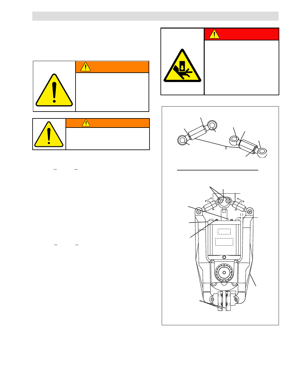
Figure 5
Do not allow air pressure to
drop during brake linkage
adjustment. High spring forces
and possible pinch points require
constant air pressure to prevent
operator injury. always keep
hands and fingers out of the
linkage assembly area when
adjusting and actuating the brake.
nOTe: The vC500 Spring actuator assembly is factory
calibrated to a 12.7 mm [0.500 in] wide brake disc. no
adjustment is necessary when mating to a disc of this
size. If using a thicker or thinner disc, offset shoes will
be required. Contact nexen for available sizes.
adjustment of linkage is required for
any disc above or below 12.4 mm [0.500
in] thick. loss of torque or failure of the
manual release function may result.
Spacing as
described in
Step 8
Actuator Cap
(Item 10)
Friction Facings
(Item 6)
Cap Screws
(Item 34)
Clevis
(Item 14)
linkage assembly
Turnbuckle
(Item 23)
Jam Nut (RH)
(Item 19)
Rod End (RH)
(Item 16)
Rod End (LH)
(Item 17)
Rod End (LH)
(Item 17)
Item 3
Actuator
Face
Jam Nut (LH)
(Item 36)
Jam Nut (RH)
(Item 19)
Jam Nut (LH)
(Item 36)
Rod End (RH)
(Item 16)
See Linkage
Assembly Above
Screw (Item 28) and
Lock Nut (Item 18)
1. If the brake is mounted and clamping on the disc,
apply >4.1 bar (>60 psi) to release the spring
actuator force from the linkage. The brake must be
disengaged and unloaded for linkage adjustment
(See Warning note to the right).
nOTe: brake shoes and detent pins must be installed
in order to perform the following procedure.
2. Remove the brake guard by removing cap screws
(Item 34) (See Figure 5).
3. Remove only the center rod ends (Item 17 & 16)
from the clevis (Item 14) by removing the locking
nuts (Item 18) and screws (Item 28).
4. Apply >4.1 bar (>60 psi) to the spring actuator.
5. With the air pressure applied rotate the clevis (Item
14) until the rear end is 100.9 mm (3.97 in) away
from the face of the actuator.
6. Insert the center rod ends (Items 16 & 17) back
into the clevis (Item 14) and tighten the locking nuts
(Item 18) to 45.2 Nm (435 in-lb).
Once the rod ends are installed, retighten the clevis
jam nut (Item 19), apply servicable thread locker to
jam nut and torque to 4.5 Nm (40 in-lb).
7. Clevis adjustment is now complete.
8. It is critical that the linkage assemblies are both
equal length. To ensure this, adjust both linkages
by rotating the turnbuckle until the spacing between
the arm (Item 3) and the actuator cap (Item 10) is
equal -- see drawing for clarification. This will create
a starting point for the final facing adjustment.
Do not wear facings down within
0.762 mm [0.030 in] of the iron
facing shoe. loss of clamping
force and machine damage will
result. monitor facing wear closely
and replace before worn to this
dimension.
WARNING