Pressure drop, Operating limits, Nsw installation manual – WaterFurnace Envision Hydronic (NSW) User Manual
Page 39: Heating with high source temperatures, Nsw vented only load side
39
NSW INSTALLATION MANUAL
Operating Limits
Heating with High Source Temperatures
Heating water with a water to water unit using high source
temperatures can lead to operating conditions that fall
outside of the system operating range. The condition occurs
when the loop (source) temperature exceeds 70°F [21.1°C]
with a full flow of 3 GPM per ton [0.054 LPS per kW].
Under this scenario, the evaporating temperature can fall
outside of the compressor operating window.
To allow the system to operate correctly, restricting the
source side flow when the evaporating temperature
exceeds 55°F [12.7°C] is recommended. One way of
accomplishing this is to use a flow-restricting valve on the
source loop circuit that is controlled by the evaporating
temperature. Locate the sensing device on the refrigerant
inlet of the evaporator.
As an alternative to the evaporating temperature, the
suction line temperature can be monitored with the same
control capability. In this control, temperature should be a
maximum of 65°F [18.3°C].
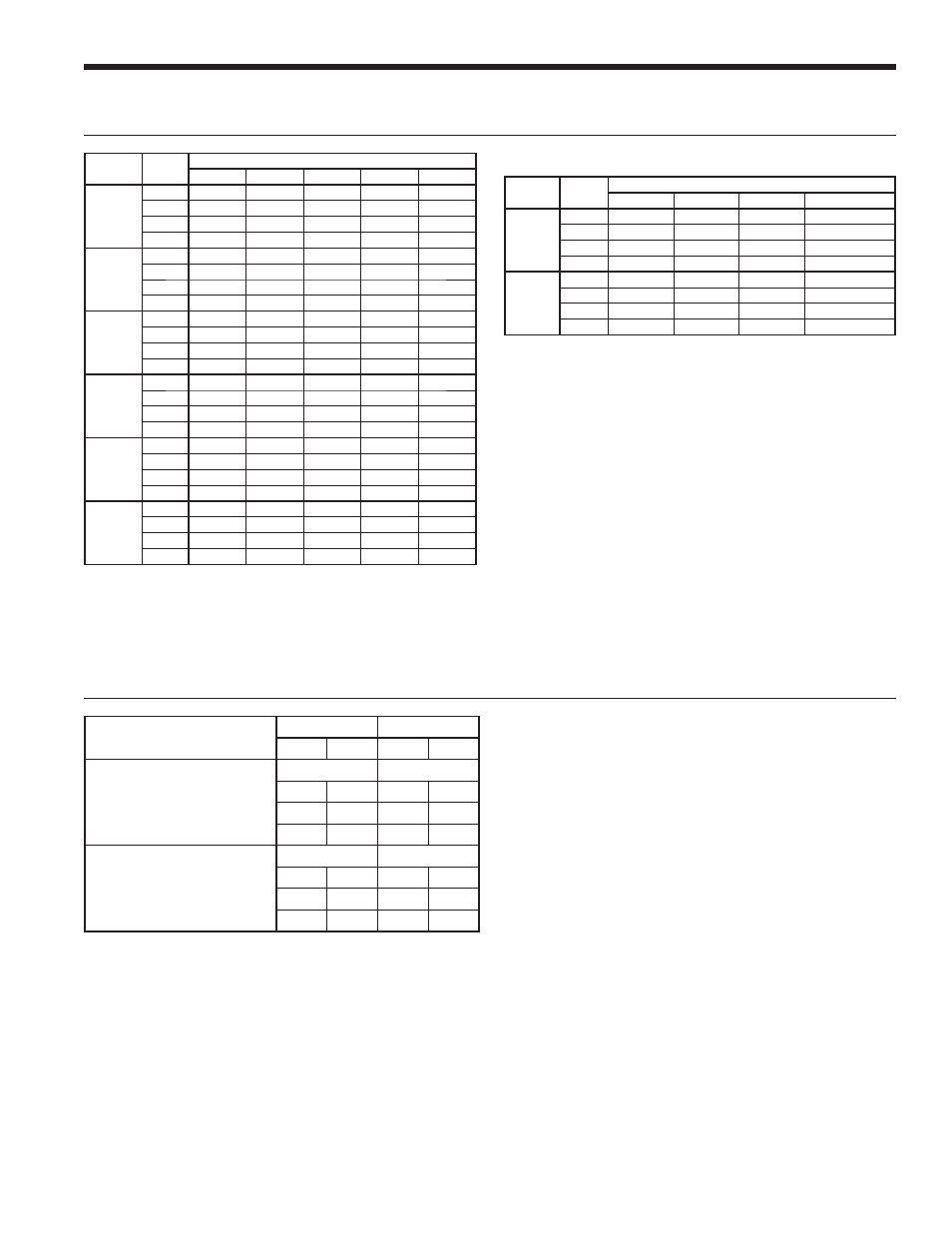
Operating Limits
Cooling
Heating
°F
°C
°F
°C
Source Side Water Limits
Minimum Entering Water
30
-1.1
20
-6.7
Normal Entering Water
85
29.4
60
15.6
Maximum Entering Water
110
43.3
90
32.2
Load Side Water Limits
Minimum Entering Water
50
10.0
60
15.6
Normal Entering Water
60
15.6
100
37.8
Maximum Entering Water
90
32.2
120
48.9
NOTES: Minimum/maximum limits are only for start-up
conditions, and are meant for bringing the space up to
occupancy temperature. Units are not designed to operate
at the minimum/maximum conditions on a regular basis.
The operating limits are dependant upon three primary
factors: 1) entering source temperature, 2) entering load
temperature, and 3) flow rate (gpm). When any of the
factors are at the minimum or maximum levels, the other
two factors must be at the normal level for proper and
reliable unit operation. Consult the Capacity Tables for each
model to determine allowable normal operating conditions.
Units are not designed for outdoor installation.
Pressure Drop
Model
GPM
Pressure Drop (psi)
60°F
80°F
100°F
120°F
018H
3.0
0.5
0.4
0.4
0.3
4.0
1.4
1.3
1.2
1.2
5.0
2.2
2.1
2.1
2.0
6.0
3.0
2.9
2.9
2.8
025H
4.0
1.3
1.3
1.2
1.2
5.5
3.0
2.9
2.8
2.7
7.0
4.6
4.4
4.3
4.1
8.5
6.7
6.5
6.4
6.2
7/13/09
NOTES: Temperatures are Entering Water Temperatures.
Double wall vented coax for heating potable water
NSW Vented Only Load Side
Model
GPM
Pressure Drop (psi)
30°F
60°F
80°F
100°F
120°F
018R*
3.0
0.5
0.4
0.4
0.3
0.3
4.0
1.1
0.9
0.9
0.8
0.8
5.0
1.6
1.4
1.4
1.3
1.3
6.0
2.1
1.9
1.9
1.8
1.8
025R*
4.0
0.7
0.6
0.4
0.3
0.3
5.5
1.3
1.1
0.9
0.7
0.6
7.0
1.9
1.7
1.5
1.3
1.2
8.5
2.6
2.4
2.2
2.0
1.9
040H/R
5.0
0.9
0.6
0.6
0.5
0.5
7.5
2.3
2.1
2.0
1.9
1.8
10.0
3.7
3.5
3.3
3.2
3.0
12.5
5.0
4.7
4.4
4.2
4.0
050H/R
8.0
1.7
1.4
1.4
1.3
1.3
11.5
3.6
3.4
3.2
3.0
2.8
15.0
5.6
5.4
5.0
4.6
4.2
18.5
8.3
8.1
7.6
7.2
6.8
060H/R
9.0
1.4
1.1
1.0
1.0
0.9
13.5
4.2
3.9
3.5
3.1
2.7
18.0
6.9
6.7
6.0
5.2
4.5
22.5
10.7
10.5
10.0
9.4
8.7
075H/R
10.0
3.2
3.0
2.8
2.7
2.5
14.5
5.5
5.3
5.1
4.9
4.7
19.0
7.9
7.6
7.3
7.1
6.8
23.5
11.5
11.3
11.0
10.8
10.5
8/9/10
NOTES: Temperatures are Entering Water Temperatures
*Domestic water heating units source side
pressure drop and reversible units load and
source pressure drop.