Pulley and spacer replacement, cont’d – Vortech 8-Rib Drive Upgrade for 2005-2009 Mustang GT User Manual
Page 12
P/N: 007084
© 2008 Vortech Engineering, LLC
All Rights Reserved, Intl. Copr. Secured.
15DEC08v1.1(007084v1.1)05MusMaxgrip
6
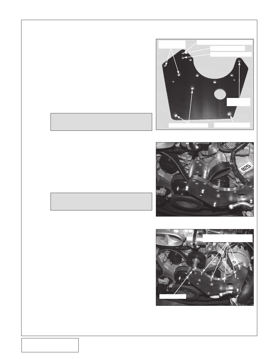
M. Install the five 3/8-16 x 1.5" supplied bolts
and washers through the back side of the
mounting plate. Install the five .280" long
spacers (2A017-878-08) onto the previously
install hardware. (See Figs. 2-d, 2-g.)
N. Attach the supercharger assembly to the
mounting plate using the previously installed
hardware and spacers. A 9/16" ratcheting end
wrench will greatly aid this step.
O. Secure the oil drain hose to the installed
brass fitting in the oil pan, making sure to
route in a smooth downward manner away
from moving or hot objects.
P.
Attach the -4 oil feed hose to the straight -4
fitting installed in the supercharger. Secure
away from moving or hot objects.
Q. Using a 1/2" ratchet, rotate the factory spring
tensioner clockwise and install the accessory
drive belt. Refer to Fig. 2-c for proper belt
routing.
R. Once the drive belt has been installed, snug
the tensioner assist bolt. Lock in place with
the previously installed jam nut.
NOTE: Any dips, “uphill” sections, kinks or restric-
tions may cause drainage problems and
possible supercharger failure.
2. PULLEy AND SPACER REPLACEMENT, cont’d
Fig. 2-f
Fig. 2-e
Fig. 2-g
PLACE .280" LONG SPACERS ON
SUPERCHARGER HARDWARE
IDLER RETAINER
2 x 8mm x
140mm SCREWS
8mm x 150mm SCREW
2 x 3/8-16 x 1.0" SCREWS
5 x 3/8-16
x 1.5" SCREWS
NON-COOLED KIT SCREW LOCATION
3/8-16 x 3.75" SCREW
H.O. KIT SCREW LOCATION
NOTE: Do not overtension the tensioner assist bolt,
as damage may occur to the OEM tensioner.
S.
Reconnect the cam sensor plug.