Pulley and spacer replacement, cont’d – Vortech 8-Rib Drive Upgrade for 2005-2009 Mustang GT User Manual
Page 11
P/N: 007084
© 2008 Vortech Engineering, LLC
All Rights Reserved, Intl. Copr. Secured.
15DEC08v1.1(007084v1.1)05MusMaxgrip
5
NOTE: Included in this kit is a smaller than originally supplied supercharger pulley. This new pulley is recommended to achieve
best performance results. Removal of the factory sealed pulley will reduce the supercharger warranty from three years to
one year unless the supercharger unit (with the original pulley still attached) and new pulley are sent into Vortech for
removal, installation and re-sealing. If supercharger warranty is not a concern or if the supercharger warranty has
expired, the pulley may simply be removed and replaced with the new part supplied. Hammering/prying etc. on the
supercharger and/or pulley will cause damage to the parts. Light heating of the supercharger pulley with a propane torch
(if the pulley is tight on the shaft) will aid removal. A return authorization number is required before the supercharger and
pulley are sent into Vortech. Call the Vortech service department at (805) 247-0226 for return authorization number.
Return freight (ground) will be paid by Vortech.
J.
S/C mounting plate re-installation:
1. Re-install the two 140mm bolts previ-
ously removed into their original
mounting plate hole locations and
slide the two original 2.691" long
spacers onto them. (See Figs. 2-d,
2-e.)
2. Re-install the idler plate onto the pre-
viously installed hardware and spac-
ers.
3. Re-install the .097" long spacer onto
the bolt that will be secured through
the alternator. (See Figs. 2-d, 2-e.)
4. Loosely install the S/C mounting
plate assembly using the original S/C
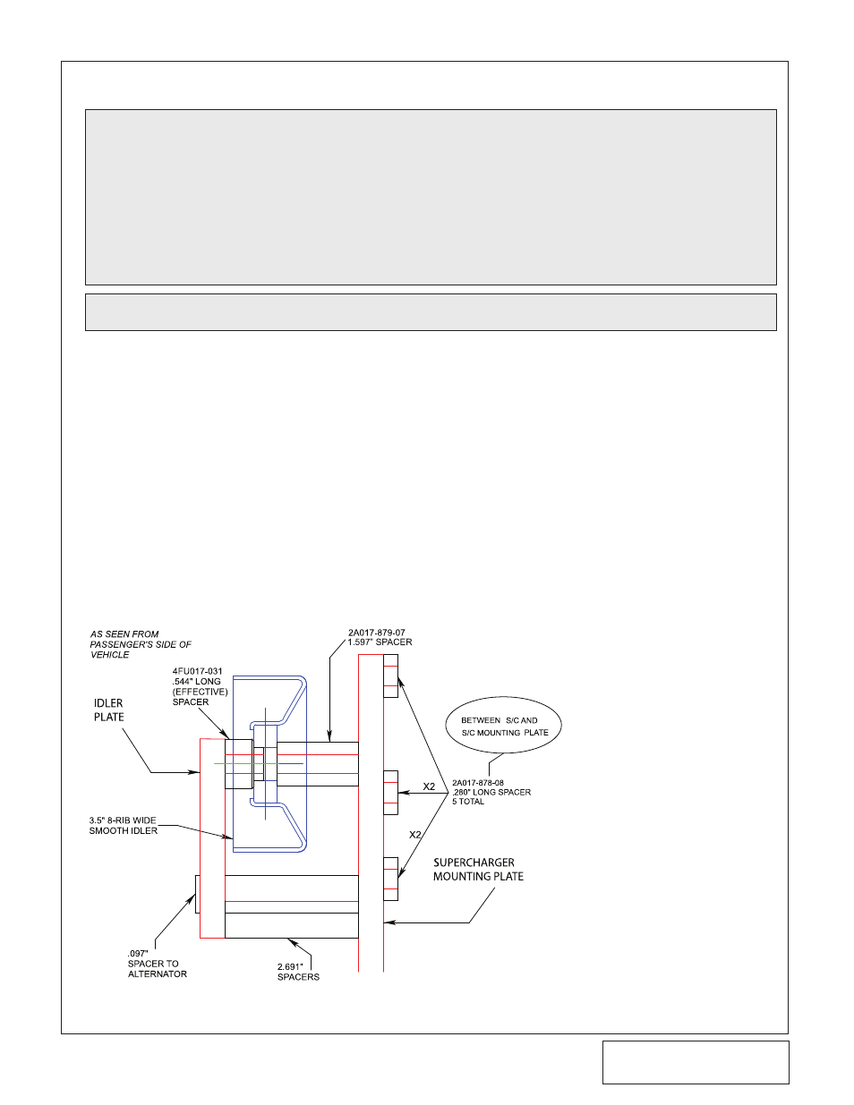
NOTE: See Fig. 2-d for the next few steps.
Fig. 2-d
2. PULLEy AND SPACER REPLACEMENT, cont’d
mounting plate hardware, taking care
to route the drive belt on the correct
side of the spacers. (See Figs. 2-f,
2-g.)
5. Locate the remaining 3.5" smooth
idler (4FU017-031), .544" long pilot
spacer, and 1.597" long spacer as
depicted in Fig. 2-d.
6. Install the idler pulley assembly refer-
encing Figs. 2-d, 2-e according to
your application ie. H.O. or standard
output.
K. Place the supercharger on a clean flat
surface with the drive pulley facing up.
L.
Remove the original 6-rib supercharger
pulley from the supercharger and install
the supplied 8-rib pulley and retainer pro-
vided.