Electronic control box installatiion. cont’d – Vortech 2003-2005 Lexus 3.0L IS300 User Manual
Page 36
P/N: 4LA020-010
©2007 Vortech Engineering, LLC
All Rights Reserved, Intl. Copr. Secured
11JUL07 v1.1 Lexus(4LAv1.1)
28
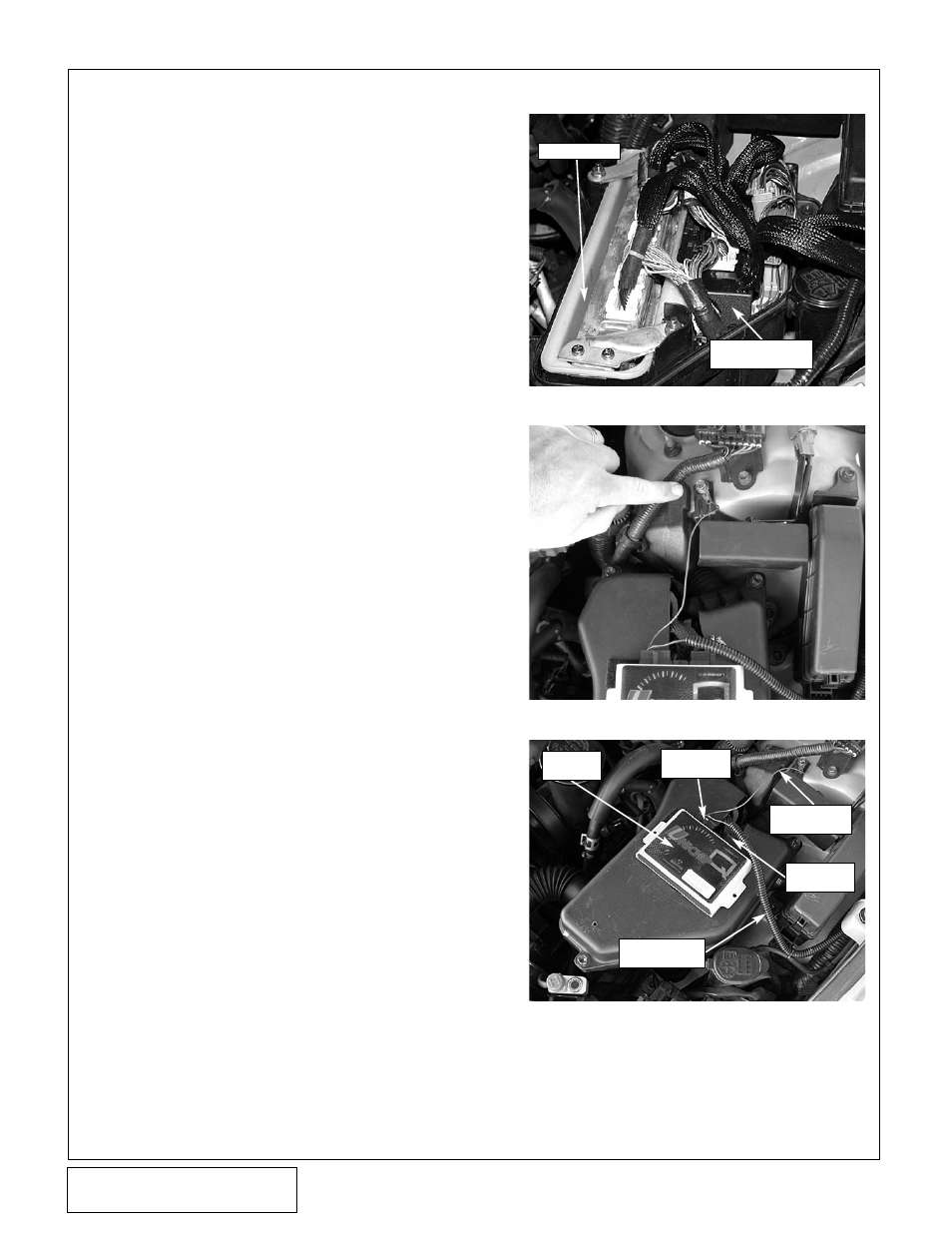
D.
Once the connections have been made, gen-
tly push the unit down into the factory ECU
housing next to the ECU. (See Fig.10-e.)
E.
Locate the factory ECU cover previously
removed and cut a hole approximately Ø1/2"
in the cover to allow the small 24-pin connec-
tor harness to pass through. Install the 24-pin
connector harness through the ECU cover.
Reinstall the ECU cover using the factory
hardware. Using the supplied Velcro installa-
tion strip, install the control module to the
ECU cover. (See Figs. 10-f, 10-g.)
F.
Connect the 16-pin and 24-pin connectors to
the control module. Install the provided ring
terminal onto the brown wires on the 16-pin
harness. Route the brown wire to the location
shown (see Fig. 10-f) and ground to chassis.
Route the red and white wire to the fuel pump
relay previously installed and connect to ter-
minal #86 as shown previously in the “RELAY
WIRING SCHEMATIC”. (See Fig. 8-i. on
page 23)
10.
ELECTRONIC CONTROL BOX INSTALLATIION. cont’d
Fig. 10-e
Fig. 10-f
Fig. 10-g
FACTORY ECU
SUPPLIED PLUG &
PLAY HARNESS
CONTROL
MODULE
16-PIN
CONNECTOR
24-PIN
CONNECTOR
BROWN
GROUND WIRE
FUEL PUMP
TRIGGER WIRE