Vortech 2003-2005 Lexus 3.0L IS300 User Manual
Page 14
P/N: 4LA020-010
©2007 Vortech Engineering, LLC
All Rights Reserved, Intl. Copr. Secured
11JUL07 v1.1 Lexus(4LAv1.1)
6
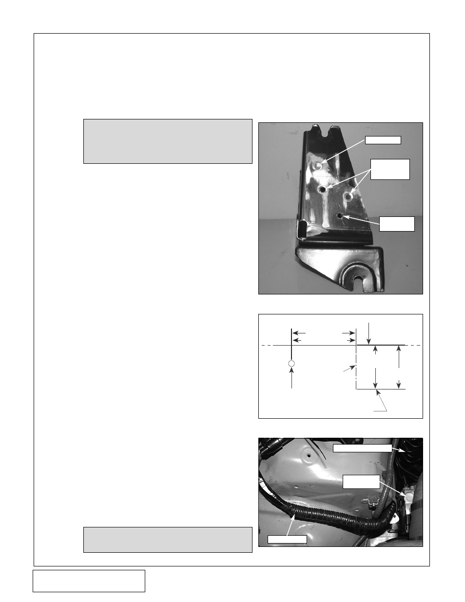
Fig. 4-a
Fig. 4-b
TOP OF FRAME RAIL
BOTTOM EDGE
OF BRACKET
FRONT EDGE
OF BRACKET
FACTORY
STUD
3.5" '02-'05 MODEL YRS
2" '01 MODEL YR
2.4" '02-'05
MODEL YRS
1-5/8" '01
MODEL YR
Fig. 4-c
A.
Locate the ABS module bracket removed in
Section 1. Remove the three spot welds that
hold the side support to the main cradle.
Separate the side support from the main cra-
dle and discard. Drill the two lower spot weld
locations to Ø3/16" and add an annitional
Ø3/16" hole as shown. (See Fig. 4-a.)
B.
(2001 Model Year Only, 2002 and Later
Skip to B-2.)
—
1.
Measure 2" back from the stud that previ-
ously secured the bottom of the ABS
bracket and make a mark. At the previ-
ously marked location, measure down 1-
5/8" from the top of a frame rail and make
a second mark. Align the front and bottom
edges of the bracket where the two marks
intersect. Using the modified bracket as a
template (see Fig 4-a) to mark the three
hole locations on the frame rail. Drill the
hole locations using a 1/8" drill bit. Secure
the ABS bracket to the frame rail using
the supplied selt-tapping hardware. Cut
the factory stud that previously secured
the ABS bracket flush wiith the frame.
(See Fig. 4-b.)
(2002-2005 Model Years Only)
,
2.
Measure 3.5" back from the stud that pre-
viously secured the bottom of the ABS
bracket and make a mark. At the previous-
ly marked location, measure down 2.4"
from the top of the frame rail and make a
second mark. Align the front and bottom
edges of the bracket where the two marks
intersect. Using the modified bracket as a
template (see Fig. 4-a) to mark the three
hole locations on the frame rail. Drill the
hole locations using a 1/8" drill. Secure the
ABS bracket to the frame rail using the
supplied self-tapping hardware. Cut the
factory stud that previoisly secured the
ABS bracket flush with the frame. (See
Fig. 4-b
.)
C.
Remove the 10mm headed screw that
secures the plastic brake line separator and
discard. Remove the brake lines from their
plastic separator located on the frame rail.
Slightly bend the lines running to the ABS
module so that it may be repositioned to its
new location. Secure the module to the relo-
cated bracket using the factory hardware.
4.
ABS RELOCATION
NOTE:
Use caution when bending these lines.
Make bends as large as possible to
avoid kinking.
NOTE:
The preferred method of removing a
spot weld is the use of a spot weld cut-
ting tool. However in this application,
the use of an approximate sized drill or
a right-angle grinder is acceptable.
D.
Locate the ABS module harness.
Carefully split the plastic flex-loom
exposing the wires from the ABS
connector to the main harness on
the shock tower. Separate enough
length to reach the relocated ABS
module and re-wrap the flex-loom.
Reconnect the harness plug to the
ABS module. (See Fig. 4-c.)
LINES SLIGHTLY BENT
RELOCATED
ABS MODULE
ABS HARNESS
SPOT WELD
NEW HOLE
LOCATION
SPOT WELDS
DRILLED
THROUGH