Vortech 1999-2000 Honda Civic Si User Manual
Page 23
P/N: 4HC020-010
©2004 Vortech Engineering, LLC
All Rights Reserved, Intl. Copr. Secured
19JAN04 99-00Honda Civic Si(4HC v3.0)
P/N: 4HC020-010
©2004 Vortech Engineering, LLC
All Rights Reserved, Intl. Copr. Secured
19JAN04 99-00Honda Civic Si(4HC v3.0)
P/N: 4HC020-010
©2004 Vortech Engineering, LLC
All Rights Reserved, Intl. Copr. Secured
19JAN04 99-00Honda Civic Si(4HC v3.0)
P/N: 4HC020-010
©2004 Vortech Engineering, LLC
All Rights Reserved, Intl. Copr. Secured
19JAN04 99-00Honda Civic Si(4HC v3.0)
15
11. AFTERCOOLER INSTALLATION, cont’d.
1.
Using thread sealant, install a 1/2” NPT to 3/4”
hose barb straight fitting into the front and side
of the surge tank (see Fig. 12-j). Insert straight
fitting into the side of the surge tank. Insert
1/8” NPT X 5/16 barb fitting into the front of
the surge tank.
2.
bolt the surge tank mounting tab to the surge
tank using the supplied 1/4-20 x 1/2” bolts and
washers.
3.
Connect the hose from the top of the reservoir
to the bottom of the surge tank and secure
with nylon clamp.
4.
Connect the hose previously installed on the air
outlet side of aftercooler core to the top of the
surge tank and secure with a nylon clamp.
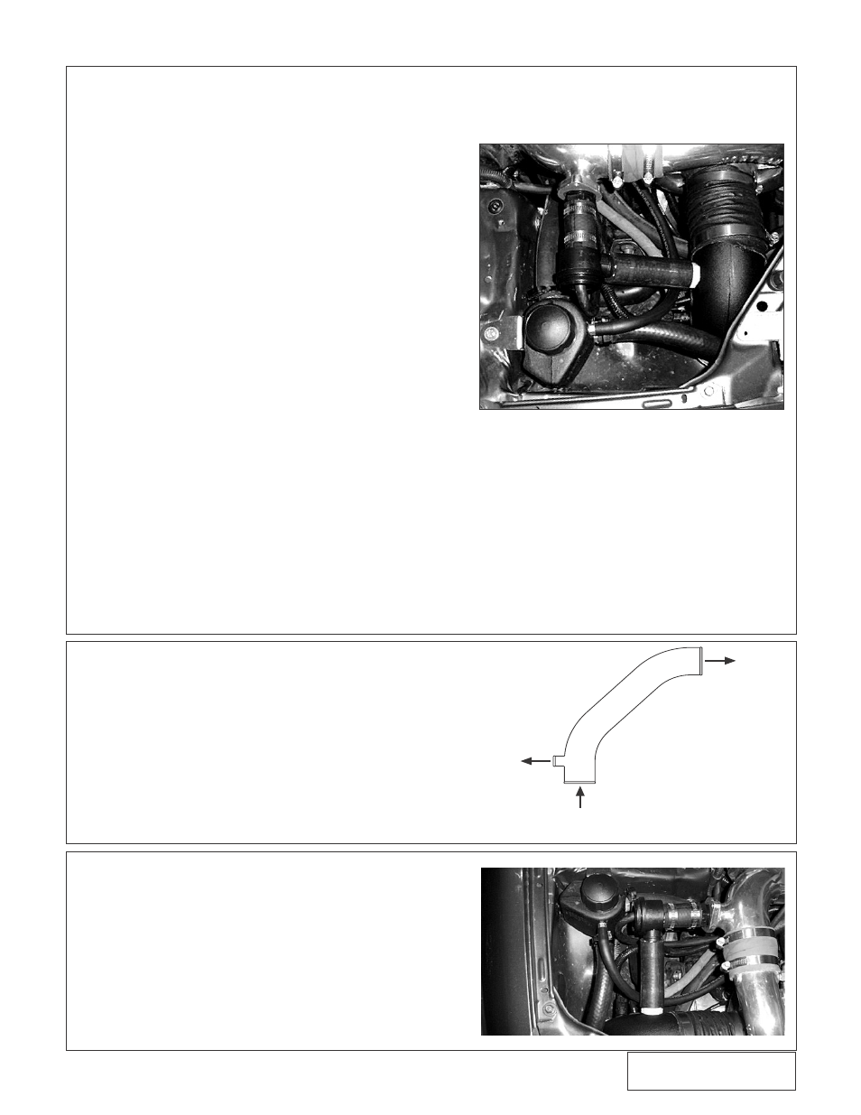
5.
bolt surge tank to passenger side strut tower
using the supplied 6mm bolt and washer. (see
Fig. 11-j)
6.
Cut the 5/16” line between the radiator and the
reservoir and install the supplied TEE. Connect
the barb fitting on the surge tank to the TEE
with the supplied 5/16” hose.
7.
Remove the cap from the surge tank and fill
the system with 25% coolant/75% water mix.
E. Surge Tank Installation
Fig. 13-a / Aftercooled bypass valve
installed (standard kit similar)
Fig. 11-j
12.
STANDARD KIT DISCHARGE DUCT INSTALLATION
A. Loosely install the supplied sleeves on both ends
of the supplied plastic discharge duct. The 2-3/4”
to 2-1/2” reducer sleeve should be placed on the
supercharger.
B. Put the discharge duct into position and slide the
sleeves onto the supercharger and the throttle
body.
C. Tighten the hose clamps on both ends of the dis-
charge duct.
FOR AFTERCOOLED SUPERCHARGER KIT INSTALLATION,
SKIP STEP 12 AND PROCEED TO STEP 13.
13.
AIR INLET DUCT INSTALLATION
A. Install the supplied 1” plastic barbed fitting, two
grommets, the air temperature sensor and the 3/8”
barbed elbow into their respective inlet duct holes
(see Fig. 13-a).
Fig. 12-a / Std discharge
duct orientation
BYPASS
VALVE
THROTTLE
BODY
SUPERCHARGER
DISCHARGE