Vortech 1999-2000 Honda Civic Si User Manual
Page 10
P/N: 4HC020-010
©2004 Vortech Engineering, LLC
All Rights Reserved, Intl. Copr. Secured
19JAN04 99-00Honda Civic Si(4HC v3.0)
P/N: 4HC020-010
©2004 Vortech Engineering, LLC
All Rights Reserved, Intl. Copr. Secured
19JAN04 99-00Honda Civic Si(4HC v3.0)
P/N: 4HC020-010
©2004 Vortech Engineering, LLC
All Rights Reserved, Intl. Copr. Secured
19JAN04 99-00Honda Civic Si(4HC v3.0)
P/N: 4HC020-010
©2004 Vortech Engineering, LLC
All Rights Reserved, Intl. Copr. Secured
19JAN04 99-00Honda Civic Si(4HC v3.0)
2
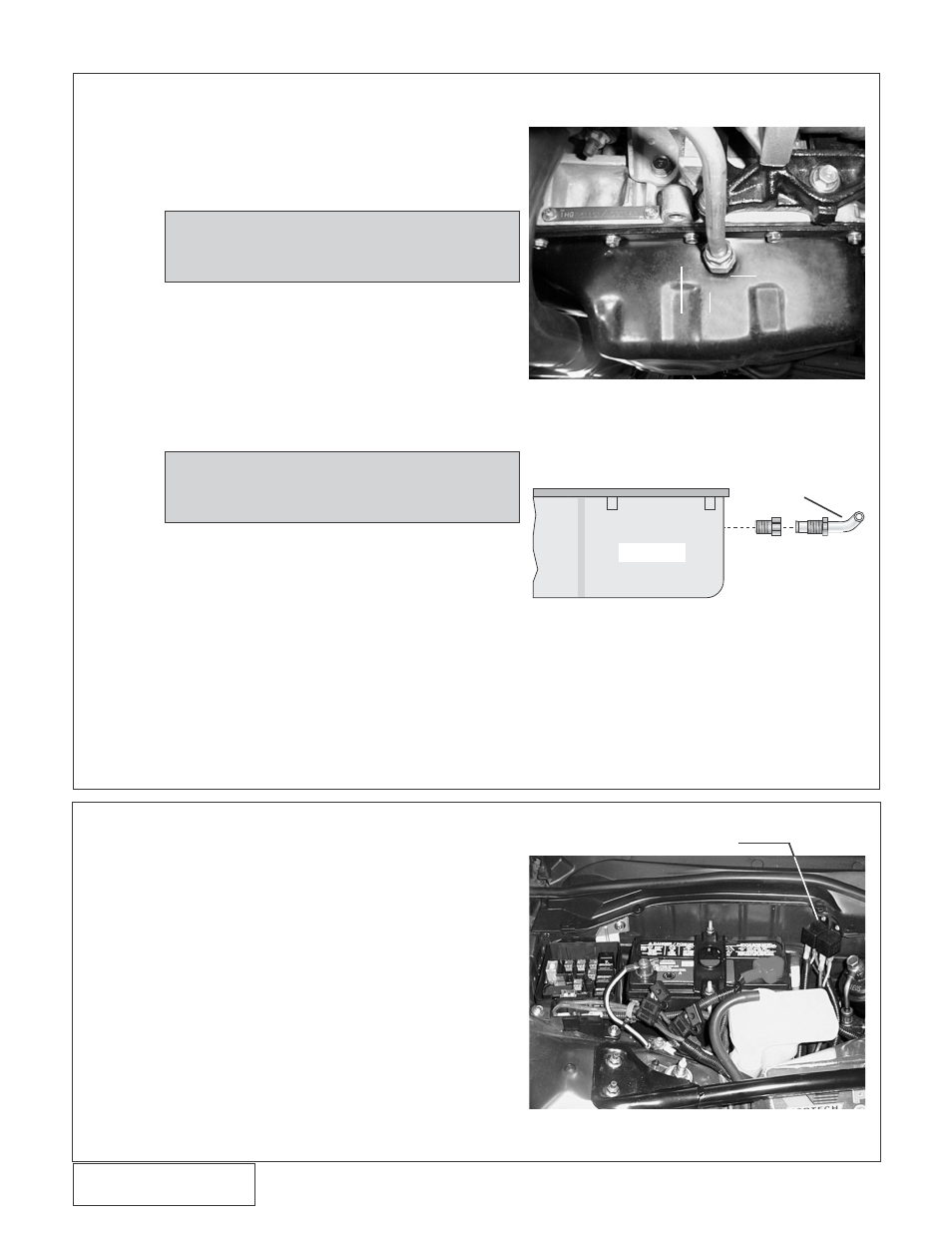
A. To provide an oil drain for the supercharger, it is
necessary to make a hole in the front of the oil pan.
Locate and center punch the hole per Fig. 3-a. This
hole should be 3/4” from bottom of oil pan lip and
centered between the stiffening ribs.
B. Remove the paint around the hole.
C. Use a small center punch to perforate the pan and
expand the hole. Switch to a larger diameter punch
and expand the hole further to approximately
ø9/16”.
D. Tap the hole with a 3/8” NPT to approximately 1/2”
deep or until the supplied drain fitting can be started.
Pack the flutes of the tap with heavy grease to hold
chips.
E. Thoroughly clean the threaded area. Apply a small
amount of silicone sealer to the new threads. Ap-
ply more sealer to the 3/8” NPT x 1/2” inverted flare
fitting and secure in the hole. Make sure that a seal
is formed all around the fitting.
F. Thread the tube nut and 1/2” aluminum tube into the
inverted flare fitting by hand. Do not tighten until
the supercharger drain hose has been connected.
G. Temporarily cover the end of the oil drain tube to
keep out debris.
H. Drain the engine oil and refill with fresh oil.
3.
OIL DRAIN
NOTE: This method of rolling over the lip of
the hole and tapping it works very well
if carefully done and should cause no
A.
Mount the supplied fuel pump relay in the location
shown in Fig. 4-a using the supplied sheet metal
screw.
B. Feed the yellow wire from relay terminal #85 through
the passenger’s side firewall (the grommet is located
behind the battery) and route behind the glove
box.
C. Open the glove box completely. (Sides of glove box
door must be pushed towards each other so that
door can fully open).
D. Locate the PGM-FI relay located to right of the glove
box. (See Fig. 4-b.) Use the supplied wiretap to con-
nect the yellow wire from the auxiliary fuel pump
relay (terminal #85) to terminal #4 on PGM-FI relay
(yellow wire with green stripe).
4.
FUEL PUMP WIRING AND INSTALLATION
Fig. 3-a
Fig. 4-a
3/4”
1”
FUEL PUMP RELAY
OIL PAN
OIL DRAIN
TUBE
Fig. 3-b / View from passenger side.
NOTE: Upon breaking through the oil pan, oil
may drain out of the newly formed hole.
Some oil may be drained from the pan if
the oil continues to flow.