Vortech 2005-2008 C6 Corvette User Manual
Page 11
P/N: 4GS020-010
©2009 Vortech Engineering, LLC
All Rights Reserved, Intl. Copr. Secured
12MAY09 v3.1 05-08Corvette(4GSv3.1)
2
A.
Remove the front wheels from the vehicle.
B.
Remove the steering rack ball joints from the
spindle on each side of the vehicle.
C.
Temporarily remove the front anti-roll bar from
the vehicle and set aside.
D.
Remove the two nuts and bolts securing the
steering rack to the cross member.
E.
Remove the two remaining screws from the
ABS mounting bracket.
F.
Remove the two screws securing the power
steering cooler (if equipped) and move the
cooler out of the way.
G. With the steering wheel pointed to the left as
far as it will go, carefully lift the rack until it
comes to a stop against the frame rail on
both sides. Move it around to provide maxi-
mum clearance.
H.
Secure the rack in this position by blocking it
up or securing it from above with tie-downs
etc. (See Fig. 2-a.)
I.
Disconnect the wiring and remove the engine
starter hardware. Push the starter forward out
of the way and install the GM J342386 fly-
wheel holding tool in the starter location to
keep the engine from spinning.
J.
Remove the crankshaft damper bolt.
K.
Install the supplied drill guide with the raised
section piloting in the damper bore. Secure in
place by installing the supplied socket head
cap screw of the correct length. Do not over-
tighten the screw as it may distort the drill
guide (its purpose is just to hold the guide in
place while drilling). (See Fig. 2-c.)
L.
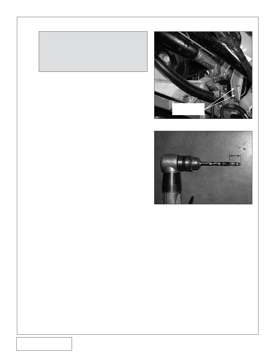
Using a small drill motor, mark a Ø1/4" drill bit
with electrical tape or a drill stop so that the
hole will be deep enough for the supplied 1/2"
long dowel pin. (See Fig. 2-b.) (The drill
bushing is 1/2" long, so with the guide
installed, the drill should go in at least 1" from
the front of the drill bushing.)
M. Make sure that when drilling the hole, the tool
remains perpendicular to the damper. Use
extra care.
N.
Remove the Socket head cap screw and drill
guide.
2. HARMONIC DAMPER DOWEL PIN INSTALLATION
NOTE: The purpose of this section is to provide access to the
harmonic damper bolt area so that the crankshaft can be
pinned to the damper to prevent the damper from spin-
ning on the crank shaft. The following steps will work on
all or most applications. If it is not possible to get ade-
quate clearance by performing the following steps, follow
the manufacturers steps for removing the harmonic
damper until there is sufficient room to work in.
Fig. 2-b
Fig. 2-a
1" MINIMUM
ABS MOUNTING
BRACKET
SCREWS