Vortech Ford SVT Contour/Mercury 2.5L V6 Cougar User Manual
Page 28
P/N: 007056
©2001 Vortech Engineering, Inc.
All Rights Reserved, Intl. Copr. Secured
31JAN01 V1.0
(Cougar (007056..SU))
© 2001 VORTECH ENGINEERING, INC.
All rights reserved. No parts of this publication may be reproduced, transmitted, transcribed,
or translated into another language in any form, by any means without written permission
of Vortech Engineering, Inc.
2
COUGAR/COUNTOUR BATTERY RELOCATION
A. To make things more accessible you will want to
remove the driver’s side headlight.
(Not neces-
sary on the Contour.)
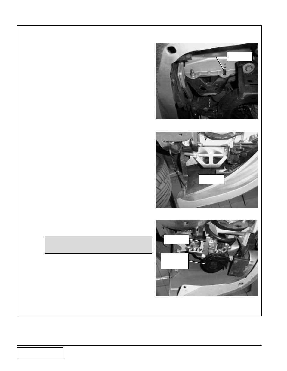
B. Remove the plastic skirting from undernearth the
front of the car to gain access to the area where
you will mount the battery. Remove the plastic
lining from the inner wheel well. The horn is
located under the driver’s side front fender. Re-
move the horn. Remove the nut from the rear bolt
holding the transport bracket. (See
Fig. 1.) Get
supplied battery box. There will be three holes in
the bottom of the battery box. Place the bottom
upward with the back closest to the outside of the
fender. Align the largest hole with a bolt located
in the fender. With the largest hole aligned mark
the smaller holes when you find a suitable posi-
tion for the box. Use a 13/32” drill bit to make the
holes. Mount the box using three provided 3/8-16
bolts and nylock nuts. (See
Fig. 2.)
C. Attach the piece of supplied foam to the battery
strap. Attach the horn to the strap using the 1/4”-
20 bolt and nylock nut on the opposite side of the
foam so that the hole lines up and the lip hangs
over the side to prevent any movement. (See
Fig. 3.)
D. Place the battery upside down (terminal down) in
the mounted battery box. Install the battery so
that the positive terminal is toward the back of the
car and the negative terminal is toward the front.
(See
Fig. 4.) Secure it with the battery strap. One
end of the strap will go into the battery box with
the foam touching the battery, while the other will
mount on the rear bolt that holds the transport
bracket. If installed properly, the horn will be
facing forward and hanging down. Connect the
horn wire. Use the stock transport bracket nut to
fasten the battery strap.
NOTE: See wiring schematic for steps “G”
and “H” (Fig. 6).
E.
Gather all the red positive wires that are attached
to the positive lead on the battery. Cut the wires
from the power distribution manifold. Take the
four wires and strip and crimp them into a sup-
plied lug end terminal (see
Fig. 6). Slide the heat
shrink tube down over the lugs and heat until the
tubing is snug over the wires. This will provide
protection to the connection. Take the end with
the battery lug terminal and route it over to the
battery. Use tie wraps to secure wires and to
keep them from interfering with themselves.
Fig. 3
Fig. 2
Fig. 1
BOX
MOUNTED
BATTERY
STRAP
HORN
MOUNTED
TO BATTERY
STRAP
REAR NUT
REMOVED