Ee “using the, Using the airfiber configuration interface – Ubiquiti Networks airFibe24 User Manual
Page 15
12
Chapter 2: Installation
airFiber
®
AF24 User Guide
Ubiquiti Networks, Inc.
Fine-Tuning the Link
The Azimuth (AZ) and Elevation (EL) Adjustment Bolts of
the Alignment Bracket adjust the azimuth and elevation
within a range of ±10°. For accurate alignment, make
adjustments on one end of the link while the other
installer reports the received signal level at the other end
of the link. Do NOT make simultaneous adjustments on
the Master and Slave.
1.
Slave
Adjust the azimuth and elevation of the Slave
until the other installer sees the strongest received
signal level displayed on the LED Display of the Master.
2.
Master
Adjust the azimuth and elevation of the Master
until the other installer sees the strongest received
signal level displayed on the LED Display of the Slave.
3. Repeat steps 1 and 2 until you achieve a symmetric
link, with the received signal levels within 1 dB of each
other. This ensures the best possible data rate between
the airFiber radios.
4. Lock the alignment on both airFiber radios by
tightening all eight Lock Bolts on the Alignment Bracket.
Observe the LED Display on each airFiber AF24 to ensure
that the value remains constant while tightening the Lock
Bolts. If the LED value changes during the locking process,
loosen the Lock Bolts, finalize the alignment of each
airFiber AF24 again, and retighten the Lock Bolts.
Using the airFiber Configuration Interface
Before You Begin
To access the airFiber Configuration Interface:
1. Make sure that your computer that is connected to the
Config port on the airFiber AF24.
2. Configure the Ethernet adapter on your computer
with a static IP address on the 192.168.1.x subnet (for
example, 192.168.1.100).
3. Launch your web browser. Type http://192.168.1.20 in
the address field and press enter (PC) or return (Mac).
4. Enter ubnt in the Username and Password fields, and
click Login.
5. The Main tab of the airFiber Configuration Interface
appears. Click the Tools drop-down list at the top right
corner of the page.
6. Click Align Antenna. You will use the Align Antenna
tool to point and optimize the antenna in the direction
of maximum link signal. (The Antenna Alignment
window is designed to refresh every 250 milliseconds.
See “Align Antenna” on page 37 for more details.)
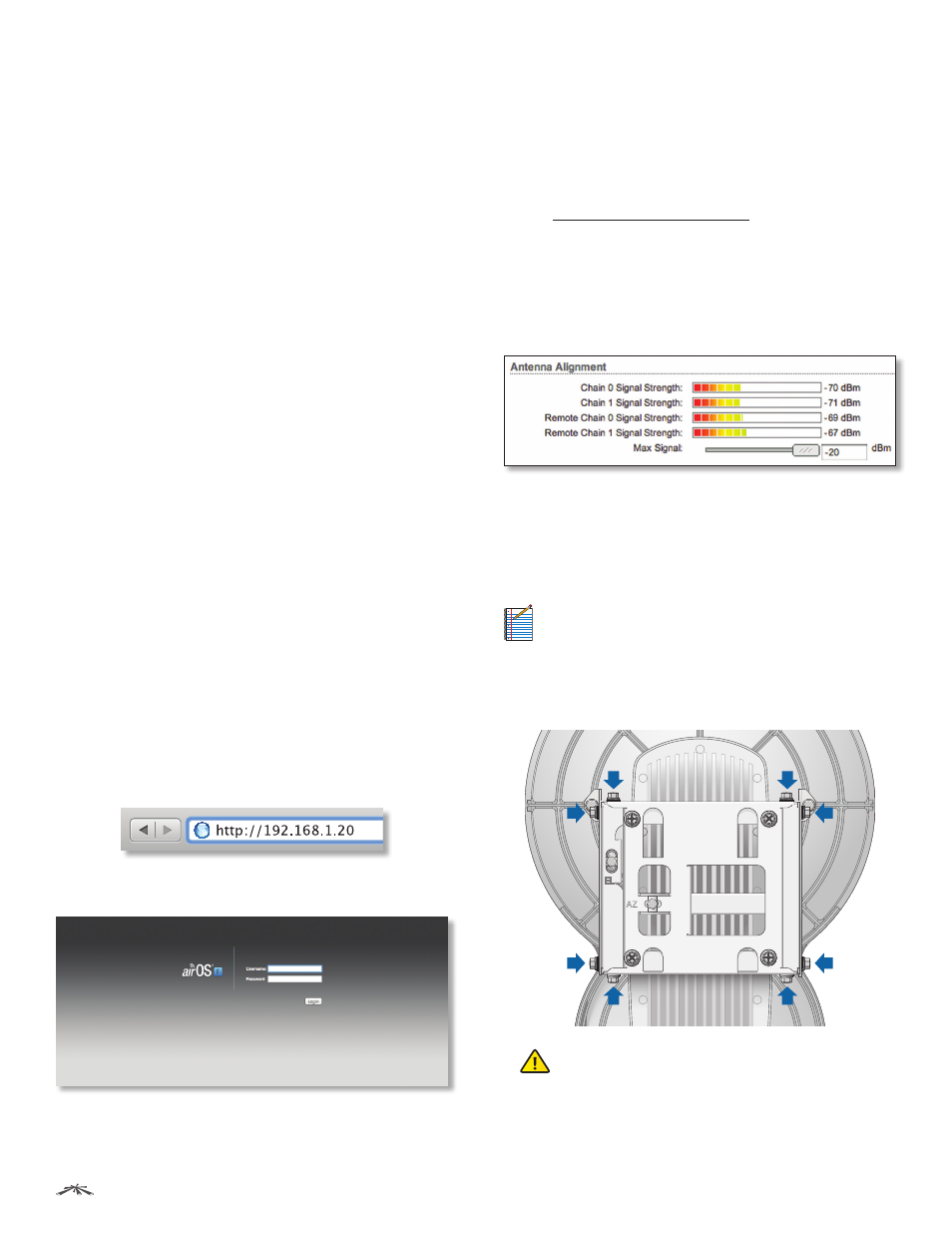
7. The Antenna Alignment window appears, displaying
the Signal Strengths for both airFiber radios. The Chain
Signal Strength bar graphs display the Signal Strengths
for the airFiber AF24 you have accessed, while the
Remote Signal Strength bar graphs display the Signal
Strengths for the other airFiber AF24.
Establishing a Preliminary Link
Adjust the positions of the Master and the Slave to
establish a preliminary link. This requires the Master
and Slave to be within a few degrees of the line of sight
between the airFiber radios.
Note:
The Master must be aimed first at the Slave
because the Slave does not transmit any RF signal
until it detects transmissions from the Master.
1. For the Master and Slave, ensure the eight Lock Bolts on
the Alignment Bracket are sufficiently loose by spinning
each washer by hand.
WARNING:
All Lock Bolts MUST be loose to avoid
damage to the airFiber housing.