2 remote control connections, 1 up/down sequence control inputs, Seq/seq-1u user manual – SurgeX SX-2120 User Manual
Page 6
© SurgeX | Technical Support: 800-645-9721 | surgex.com
Page 6
SEQ/SEQ-1U
User Manual
Software Version 2.0
3.2 Remote Control Connections
Remote connections are wired to the green 7-pin plug-in Phoenix terminal block on the rear of the unit next to the
power cord. The terminal block itself is shipped in the accessory bag. After you have made the connections to the
terminal block, plug it into the connector on the rear of the unit. Never solder (tin) wires before inserting in a
terminal block – solder creeps and you will eventually have loose connections!
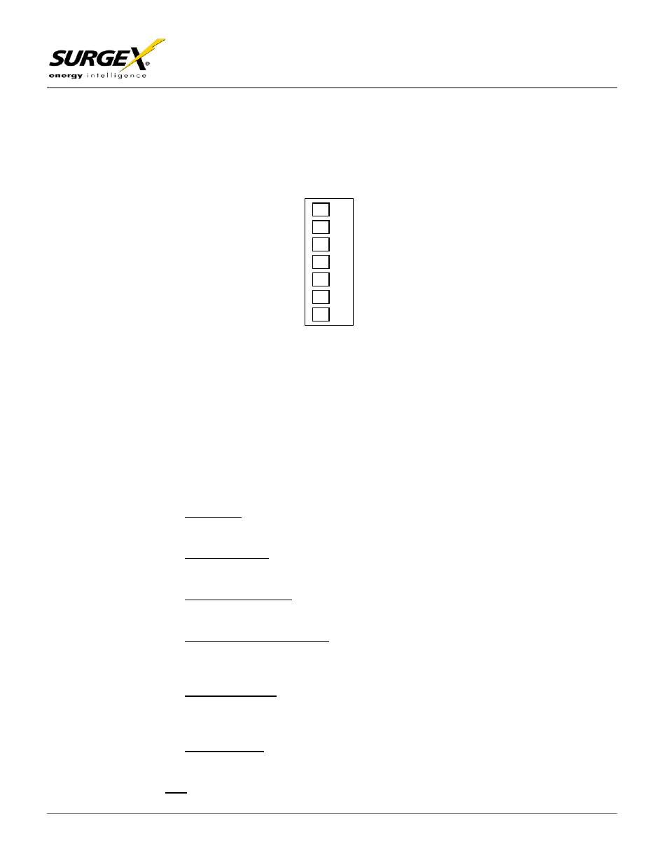
The connections are shown here:
3.2.1 Up/Down Sequence Control Inputs
The SEQ can be controlled by a DC voltage in the range of 5V to 30V, by a contact closure (such as a
relay), or by a switch. In this manual the terms “momentary” and “latching” are used when describing
switches. A momentary switch is considered to be a switch which provides a connection only while it is
actually held pressed, and a latching switch is considered to be a switch which remains in either the on
or the off state (like a light switch). Momentary switches are preferred for use with the SEQ since
multiple control locations can be used, and also because some of the functions of the SEQ are not
available when a latching switch is used (see programming section). Switches with gold contacts are
recommended for the best long-term reliability. The type of input is selected totally through
programming, making the electrical connections straightforward. The six control options are discussed
below:
a) DC
V
OLTAGE
: The SEQ will power up when the voltage is present and power down when there is no
voltage. Connect the positive wire to the “Up” input, and the ground (or negative) wire to “Common”.
Program the input for “5-30 V DC”.
b) C
ONTACT
C
LOSURE
: The SEQ will power up when the contacts are closed and power down when
the contacts are open. Connect the two wires from the contacts to “Up” and “Common”. Program
the input for “Latching”.
c) M
OMENTARY
S
WITCH
(
ES
): The SEQ will power up when a switch is pressed once and power down
when a switch is pressed a second time. Connect the two wires from the switch(es) to “Up” and
“Common”. Program the input for “Momentary”.
d) S
EPARATE
U
P
&
D
OWN
S
WITCHES
: The SEQ will power up when the UP switch is pressed and power
down when the DOWN switch is pressed. Connect the two wires from the UP switch to “Up” and
“Common”, and the two wires from the DOWN switch to “Down” and “Common”. Program the input
for “Separate Up & Down”.
e) C
ENTER
-O
FF
S
WITCH
: The SEQ will power up when the switch is pressed to the UP position and
power down when the switch is pressed to the DOWN position. Connect the wire from the UP
terminal to “Up”, the wire from the DOWN terminal to “Down”, and the wire from the COMMON
terminal to “Common”. Program the input for “Separate Up & Down”.
f) L
ATCHING
S
WITCH
: The SEQ will power up when the switch is closed and power down when the
switch is open. Connect the two wires from the switch to “Up” and “Common”. Program the input for
“Latching”.
Note: The front panel button will not operate with options a, b or f
Pin 1 – Up Input
Pin 2 – Down Input
Pin 4 – 12 V DC Output
Pin 5 - Common
Pin 6 – Aux Relay Contact
Pin 7 – Aux Relay Contact
Pin 3 – Over-Ride Input