Seq/seq-1u user manual – SurgeX SX-2120 User Manual
Page 18
© SurgeX | Technical Support: 800-645-9721 | surgex.com
Page 18
SEQ/SEQ-1U
User Manual
Software Version 2.0
As can be seen in the above two examples, by choosing the appropriate sync setting and delay times it is
possible to position the 4
th
bank anywhere in the sequence.
If an over-ride is used with an expanded system do not use the Special Delay because the 4
th
bank may not turn
on and off in the correct sequence during an over-ride condition.
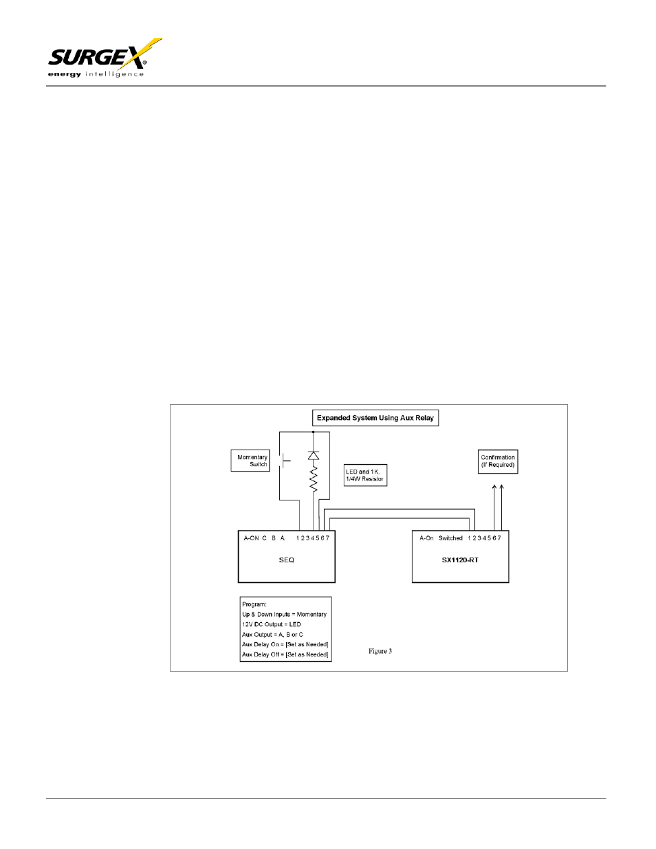
Figure 4 (page 17) shows how to configure an expanded system using the 12V DC output instead of the Aux
Relay to control external units. This option allows the aux relay to be used for confirmation but it is then no longer
possible to drive external LEDs from the 12V DC output. The programming and delay timing set up follow the
same concepts as for the aux relay which is explained above.
Figure 5 (page 17) shows an example of a medium-sized system where the SEQ is controlling two separate sets
of equipment independently by using both the aux output and the 12V DC output as control outputs. The
equipment rack is controlled by the 12V DC output and the bank of amplifiers is controlled by the aux output (via
SX1120RTs). The signal processing equipment is powered from the SEQ itself. Control wiring and programming
is as per Figures 3 and 4. Figure 5 is just one example of the versatility of the SEQ, and the banks do not have to
be set up exactly as shown in this example. The aux output and the 12V DC output could be programmed to be
the first two sequenced banks, or the last two sequenced banks. Similarly, the rack-mount SX1120RT remote
turn-on SurgeX was used in this example whereas the ICE20C or the hard-wired SX20-NE/RT could equally have
been used.