Installing the receiving frame – StorCase Technology DE300i-S User Manual
Page 19
DE300i-S User's Guide - Rev. B00
Kingston Technology Company
Installation
13
Installing the Receiving Frame
The drive should be installed into the carrier before installing the receiving frame into the
mounting bay of a computer or expansion chassis.
NOTE:
Use a #2 Phillips screwdriver during this procedure.
1.
Turn off power to the computer.
2.
Open the computer system according to the manufacturer’s instructions. If
necessary, temporarily remove any expansion boards that may make installation
difficult.
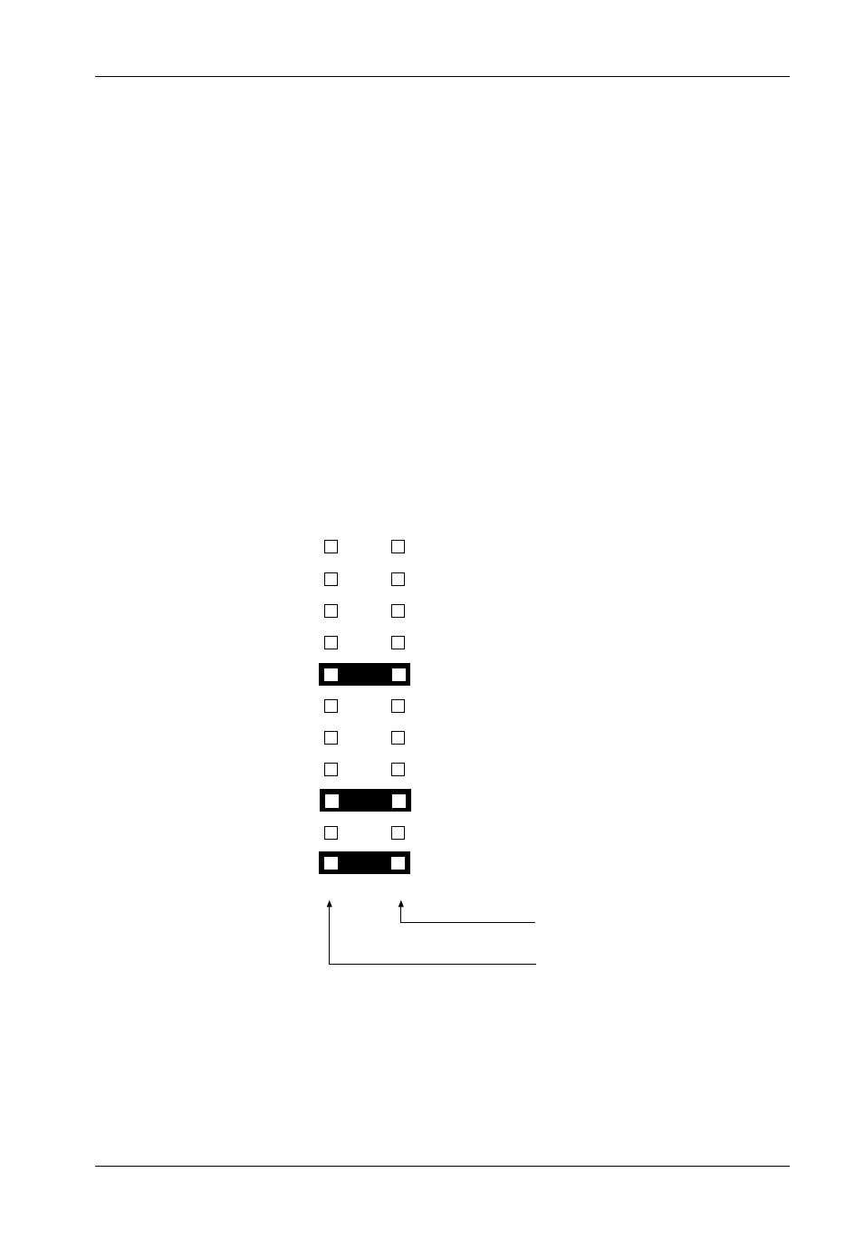
3.
To select the Data Express unit ID remotely through the computer system or
external expansion chassis, the appropriate cable from the system must be
connected to option pins (1-8 on connectors J3A, J3B, J3C) on the rear of the
receiving frame (Figure 5). Set the unit ID to '0' for remote ID selection (Figure 13).
0542A
Pin 1
Pin 2
ID0
Pin 3
Pin 5
Pin 7
Pin 9
Pin 11
Pin 13
Pin 15
Pin 17
Pin 19
Pin 21
Pin 4
ID1
Pin 6
ID2
Pin 8
Not Used
Pin 10 DT (Factory Installed Jumper)
Pin 12 RLED
Pin 14 DF
Pin 16 SYNC
Pin 18 TPWR
Pin 20 WTP
Pin 22 LK (Factory Installed Jumper)
Ground
Row
Signal
Row
Figure 11: Receiving Frame Motherboard J3A, J3B, J3C Option Pins