The receiving frame rear panel – StorCase Technology DE300i-S User Manual
Page 12
6
Introduction
Kingston Technology Company
DE300i-S User's Guide - Rev. B00
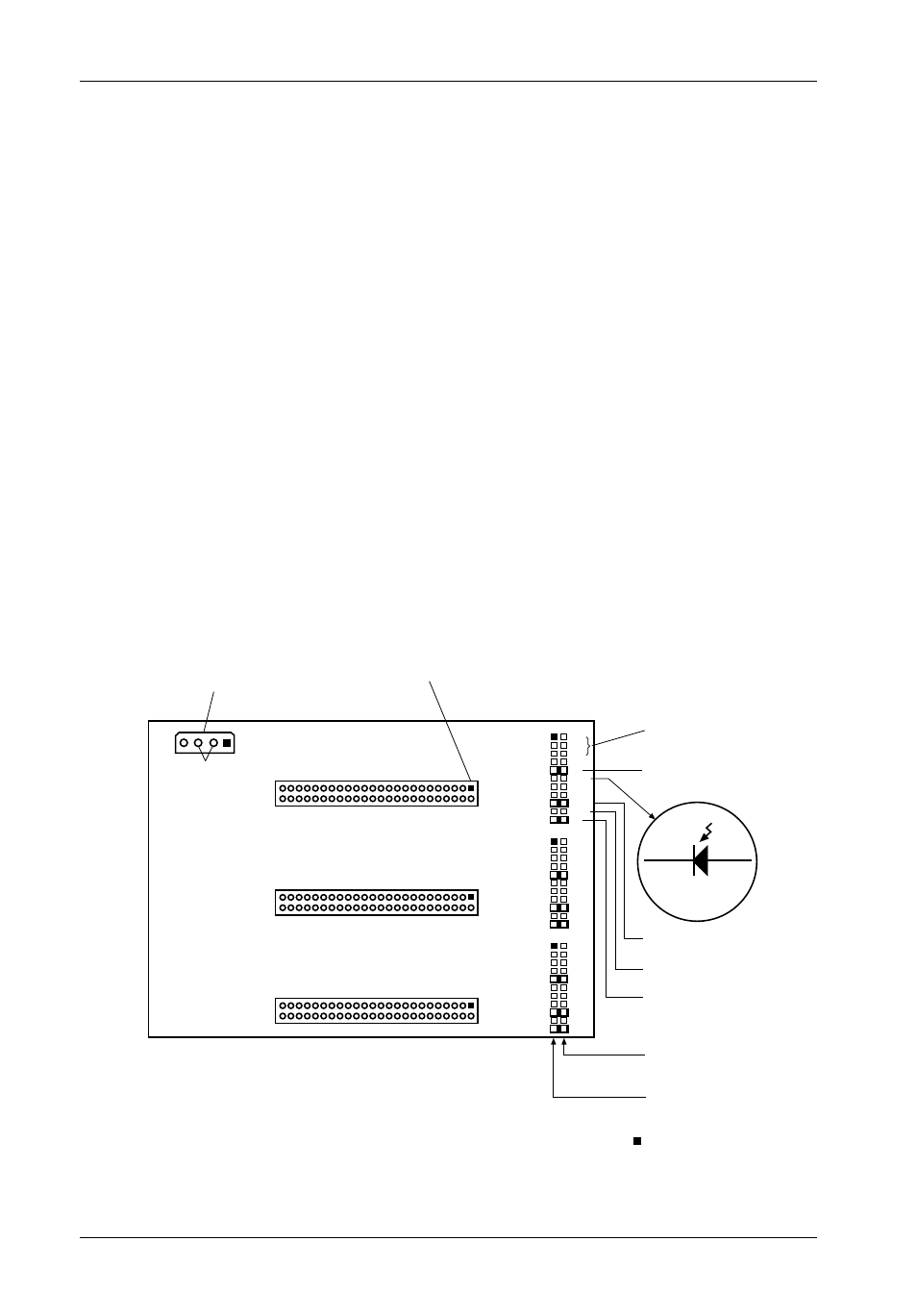
The Receiving Frame Rear Panel
• I/O Connectors (J3, J4, and J5) - These connectors provide a standard interface for all
SCSI signals (Figure 5). See Table 3 for pin assignments.
• DC Power Connector (J6) - A standard 4-pin Molex power connector is used to accept
DC power.
• ID Select Connectors (J3A, J3B and J3C) - Pins 1 through 6 of these connectors
provide SCSI unit ID selection for the computer system or expansion chassis. For
remote ID selection through an expansion chassis, an appropriate cable must be
attached to these pins and the unit ID must be set to "0". The unit ID can be set with a
rotating switch located inside the receiving frame (Figure 13).
• Disable Termination (DT) - A factory installed jumper on these pins disables termina-
tion. Removing this jumper will enable termination. Remove this jumper if the drive is
physically located at the end of a SCSI daisy chain.
• Remote Activity LED (RLED) - These pins provide power for a remote LED device
activity indicator. (Pin 11=Cathode, Pin 12=Anode.)
• Enable Termination Power To/From SCSI Bus (TPWR) - This jumper is installed at the
factory.
Figure 5: Receiving Frame Mother Board (Rear View)
ID0
ID1
ID2
DT
RLED
DF
SYNC
TPWR
WTP
LK
DC Power
Connector
Ground
Row
J6
+5
+12
GND
1
21
J3A
J3B
J3C
1
1
Remote ID
Select
Anode
Cathode
P11
P12
Remote
Activity LED
Disable On Board
Terminaton
(Installed
at Factory)
SCSI I/O Connector (Pin 1)
J3
Signal
Row
21
21
Term. Power
To/From SCSI Bus
0503A
= Pin 1
J4
J5
ID0
ID1
ID2
DT
RLED
DF
SYNC
TPWR
WTP
LK
ID0
ID1
ID2
DT
RLED
DF
SYNC
TPWR
WTP
LK
Reserved