StorCase Technology DE300i-S User Manual
Page 18
Kingston Technology Company
DE300i-S User's Guide - Rev. B00
12
Installation
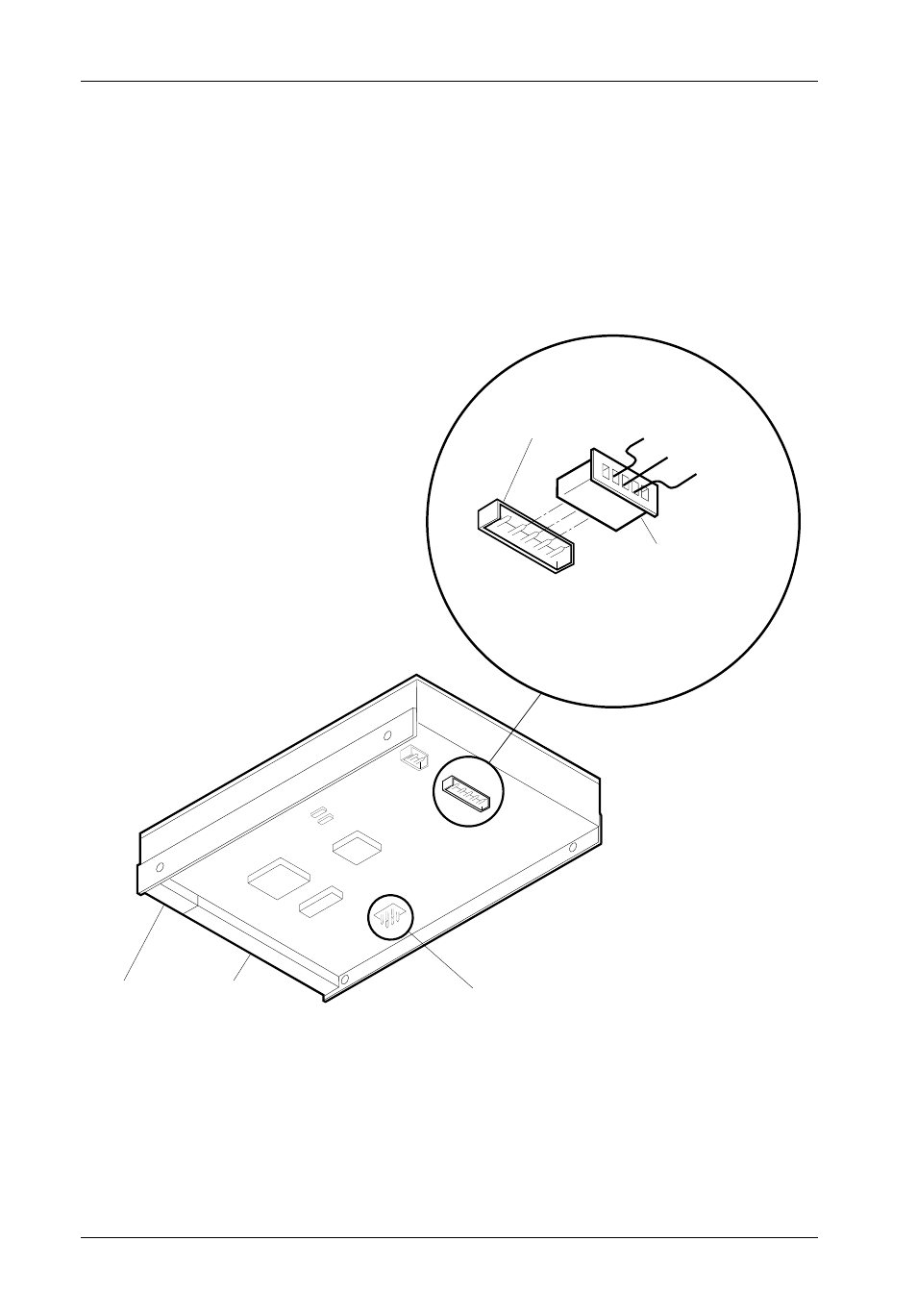
TYPICAL 1.25MM DRIVE ID PIN CONFIGURATION
Figure 10 illustrates a typical SCSI ID select connection to a drive with 1.25mm ID select pins.
Attach the .1 inch/1.25mm ID select cable to the drive using the 1.25mm connectors. Align the
“ID0” pin with the black wire. Attach the other end of the ID select cable to the ID select
connector located on the carrier board, inside the drive carrier. Refer to the manufacturer’s
documentation to disable termination on the drive.
SCSI ID Select
Cable (from Data
Express Signal
Distribution Board)
1.25mm connector
SCSI ID Selection
Connector J5 (located
on disk drive PCB)
SCSI I/O
Connector
Power
Connector
A0 (Black)
A1 (Brown)
A2 (Red)
A0
A1
A2
SCSI ID Selection
Pins JP1 (located on
disk drive PCB)
When Using J5,
Remove all Jumpers
From JP1
0208
R
e
s
e
r
v
e
d
G
n
d
Figure 10: Quantum 540S (Typical 1.25mm Pin Connection)
- DE100i-SW (35 pages)
- DE110 (33 pages)
- DE110 (2 pages)
- DE110 (31 pages)
- DE110 (27 pages)
- DE50 (33 pages)
- DE50 (27 pages)
- DX115 (25 pages)
- DE75i-A (31 pages)
- DE75i-A66 (29 pages)
- DE75i-A100 (31 pages)
- SATA DE75 (28 pages)
- DE75i-S (31 pages)
- DE75i-SW (33 pages)
- DE75i-SWC (33 pages)
- DE75i-SW160 (29 pages)
- S20A114 (29 pages)
- DE75i-SWC160 (29 pages)
- DE90i-A (29 pages)
- DE90i-A66 (23 pages)
- DE90i-A100 (23 pages)
- DE90i-S (25 pages)
- DE100i-A (33 pages)
- DE100i-A66 (29 pages)
- DE100i-A100 (29 pages)
- DE100i-CSWTN (2 pages)
- DE100i-S (39 pages)
- DE100i-SWD (33 pages)
- DE100i-SWU2 (37 pages)
- DE100i-SWCU2 (33 pages)
- DE100i-SWU2X (35 pages)
- DE100i-SW160 (35 pages)
- S20A102 (33 pages)
- DE100i-SWC160 (39 pages)
- Ultra320 DE100 (31 pages)
- DE110 (27 pages)
- DE110 (31 pages)
- DE110 (29 pages)
- DE150i-SWC (33 pages)
- DE200i-S (33 pages)
- DE200i-CSWTN (2 pages)
- DE200i-SW (35 pages)
- DE200i-SWU2 (37 pages)
- DE200i-SWCU2 (35 pages)
- S20A108 (33 pages)