StorCase Technology DE300i-S User Manual
Page 11
Introduction
5
DE300i-S User's Guide - Rev. B00
Kingston Technology Company
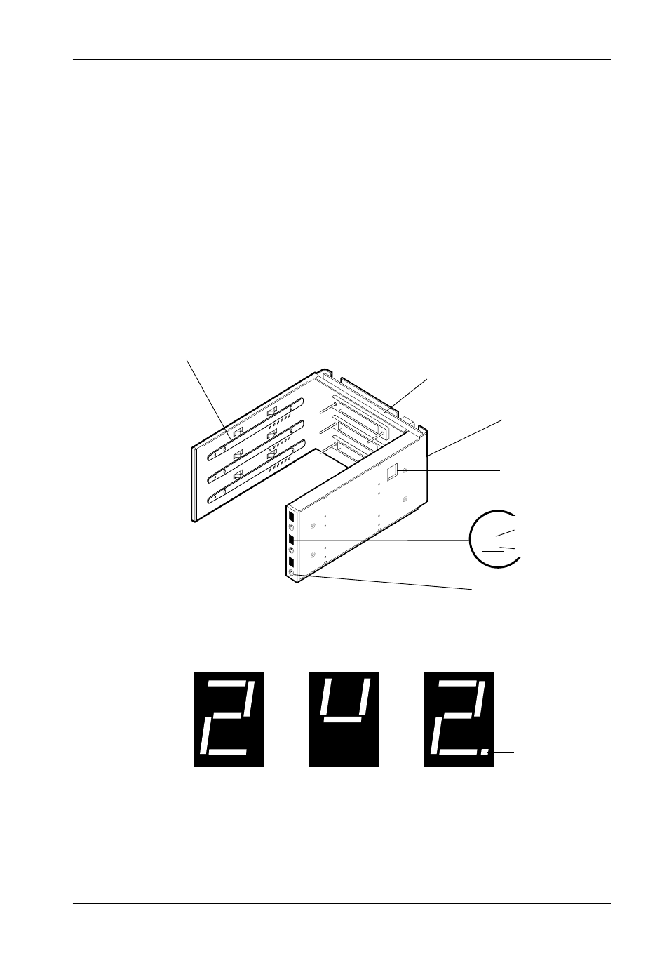
Figure 4: Unit Number Display Conditions
Carrier Installed
(unlocked)
Carrier Installed
(locked)
Carrier Removed
from Receiving Frame
The number '2' shown above is for illustration purposes only. It
can be any valid Unit ID number. However, the letter 'U' (above
middle), will appear as illustrated.
0064
Activity
Indicator
Receiving
Frame
Key/Lock
and Power
Switch
2.
Unit Number
Display
Activity Indicator
0511
Carrier Guide
High Insertion
Count Mating
Connector
All Steel
Receiving
Frame
Spin
Down/Up
Timer
•
Unit Number Indicator (Figures 3 and 4) - This LED displays the status of the
drive carrier. A unit number is displayed when the carrier is
installed and locked
into the receiving frame or
if the carrier is removed from the receiving frame. If
the carrier is installed in the receiving frame but
unlocked, a "u" will be displayed.
The unit number is set by means of the unit select switch located inside the
receiving frame using a special alignment tool supplied with the Data Express
(see Figure 13).
•
The Activity Indicator (Figures 3 and 4) - A small dot next to the unit number
illuminates to indicate when the host computer is accessing the data on the Data
Express carrier. This dot will flash during communication with the host computer.
•
Device Spin Down/Up Timer (Figure 3) - This timer controls the length of time
that the unit number display flashes during device spin down/up, providing a
visual indication of drive activity. Refer to Figure B-3 for switch settings.
Figure 3: Receiving Frame Front Panel