Receiving frame (rear) – StorCase Technology DE200i-SWC160 User Manual
Page 12
Introduction
5
DE200i-SWC160 User's Guide - Rev. B01
StorCase Technology, Inc.
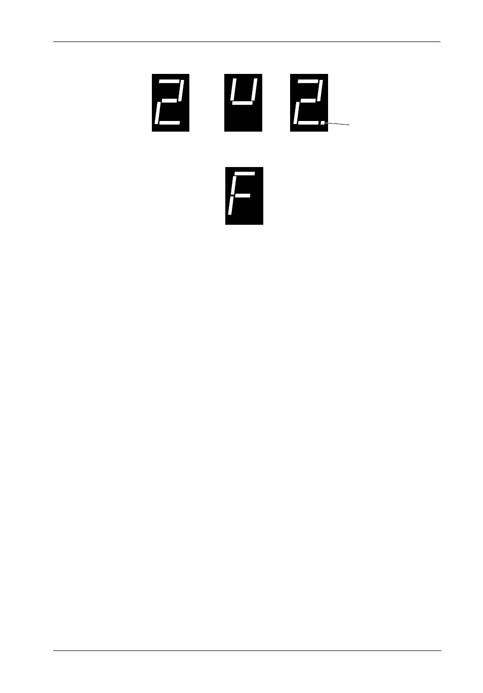
Figure 4: Receiving Frame Unit ID Number and Activity Display
Receiving Frame (Rear)
(Figure 5)
DC Power Connector (P1): The DE200i-SWC160 uses a standard 4-pin DC power
connector to accept DC power.
I/O Connector (J2) : The input/output connector provides a standard interface for
16-bit wide SCSI signals.
Buzzer: Buzzer will sound in the case of a fan failure.
Option Pin Connector (W1):
Remote Unit ID Selection: Pins 1-8 of this connector are provided for remote unit
SCSI ID selection through the computer system. Remote ID selection requires that the
unit ID switch located on the inside of the receiving frame be set to "0". (Onboard ID
selection is set with a switch located on the inside of the receiving frame as shown
in Figure 10). See Table 1 for pin assignments.
Factory-Installed Jumpers: There are three (3) jumpers factory-installed on W1.
These jumpers are located on Pins 9 & 10, Pins 19 & 20, and Pins 21 & 22.
NOTE: Do not remove these jumpers!
Carrier Installed
(unlocked)
Carrier Installed
(locked)
Carrier Removed
from Receiving Frame
The number "2" shown above is for illustration purposes only. It can be any valid
unit ID number. The letter "u" and F will appear as illustrated.
0064c
Activity
Indicator
Fan Failure