SOR 141 Differential Pressure Switch User Manual
Differential pressure switches, General instructions, Installation
Form 1307 (04.13) ©SOR Inc.
1/4
131/141 Nuclear-Qualified
Differential Pressure Switches
General Instructions
NOTE: If you suspect that a product is defective, contact the factory or the SOR
®
Representative
in your area for a return authorization number (RMA). This product should only be installed by
trained and competent personnel.
Installation
Mount pressure switch to rigid vertical mounting surface with four 1/4-20 Grade 5 screws
(not supplied). Torque screws to 70 - 85 in/lbs. The 141 must be oriented with the sensor
down (housing up).
Design and specifications are subject to change without notice.
For latest revision, go to www.sorinc.com
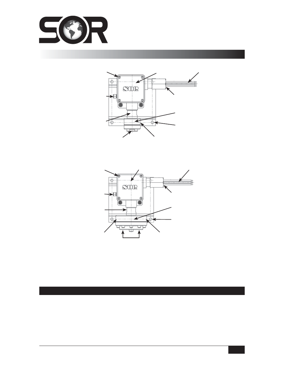
141
Cover Screws
1/8” NPT(F) Vent Connection
Body
Mounting Holes
Wire Leads
Housing
3/4” NPT(F) Conduit Connection
High Side Process Connection
Low Side Process Connection
Low Side Process Connection
Sensor
131
Cover Screws
1/8” NPT(F) Vent Connection
Body
High Side Process Connection
Mounting Holes
3/4” NPT(F) Conduit Connection
Wire Leads
Low Side Process Connection
Housing
Sensor