SOR 1530 Pneumatic Level Switch User Manual
Page 2
2/4
Form 439 (04.13) ©SOR Inc.
Before Installing the Level Switch
Inspect the unit for any shipment damage.
Check for mechanical clearance. The float must move freely throughout its stroke inside
the vessel.
Use an acceptable thread compound to ensure a leak free fit and avoid thread galling
when installing the unit into the vessel.
The unit may be mounted in any of the following installation arrangements:
2” NPT full or half coupling
3” NPT full coupling (Use in conjunction with 2 x 3” NPT bushing.)
Optional flanged mounting
Optional chamber mounting
Clean dry air or gas must be used as the supply media to avoid plugging critical internal
restrictions and nozzles.
SUPPLY PRESSURE RANGE: 20 TO 60 PSIG
Installation
Connect the supply line to the 1/8” NPT connection stamped Supply. Do not use pipe
compound on the first two threads on pneumatic fitting. The supply media must be
filtered and oil free. Air is the usual media; however, any dry filtered gas can be used.
Connect the output port stamped Output to the unit to be controlled.
NOTE: If the controlled device has a volume of less than 15 cubic inches, the small volume may
cause the output to fl uctuate. The addition of output volume will stop this fl uctuation.
VENTING CAUTION: Note the position of the vent connection on the body. It must
be positioned on a horizontal axis either on the right or the left side of the body.
This connection must not be plugged. It is used for either local atmospheric
venting or remote venting through a suitable line run to the designated venting
area. Supply or Output connections must not be connected to the Vent port.
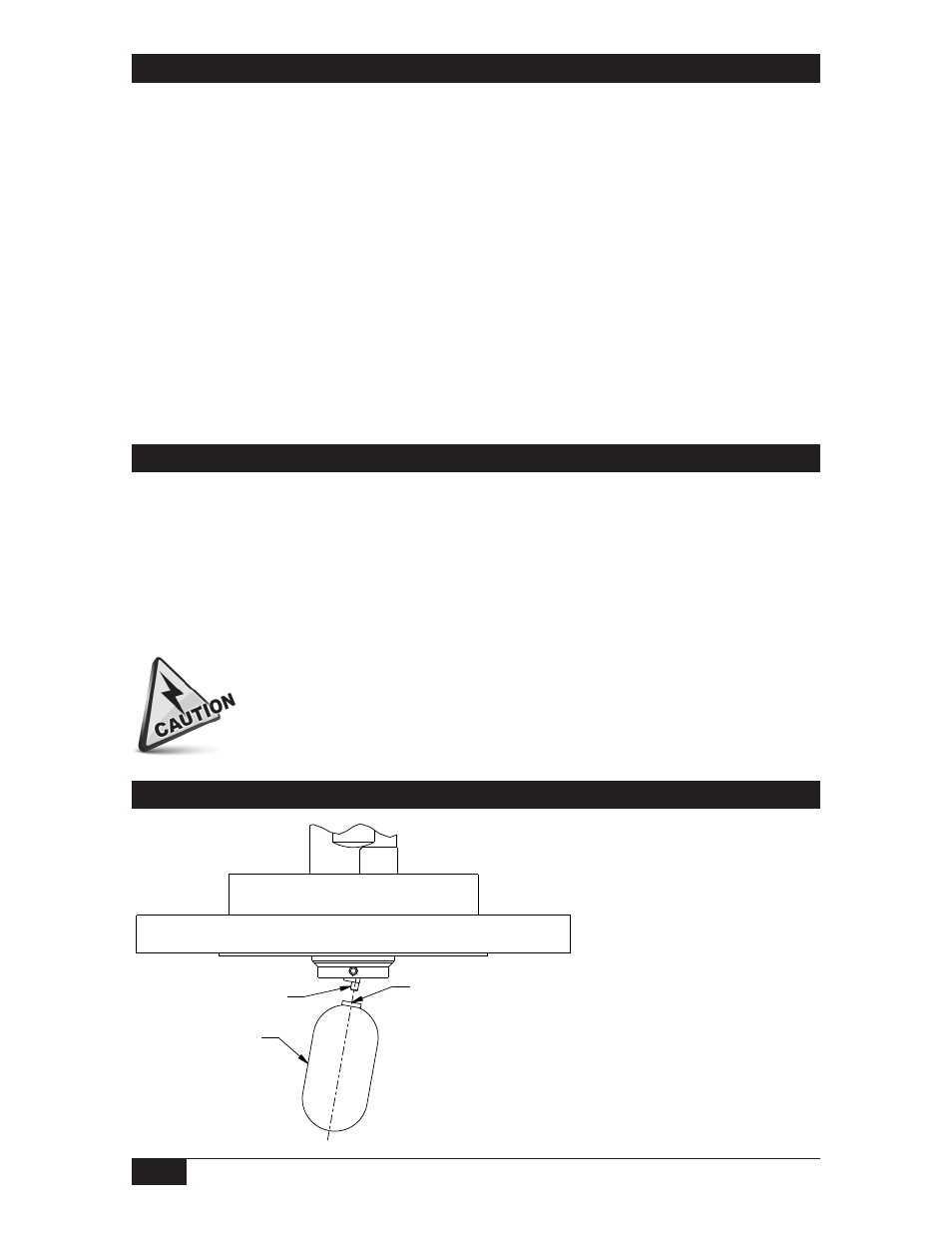
Float Attachment
APPLY TWO DROPS
LOCTITE 271 INSIDE
THREADED HOLE
OF FLOAT
FLOAT
SET SCREW
Place two drops of Loctite
271 inside the threaded
hole of the float.
Thread the float onto the set
screw and hand-tighten.
Linear = mm/inches
Drawing 0390747
NOTE: Do not remove the set
screw as it secures the pivot
arm to the shaft.