SOR 1520 OEM Flow Switch User Manual
Page 2
2/8
Form 454 (11.13) ©SOR Inc.
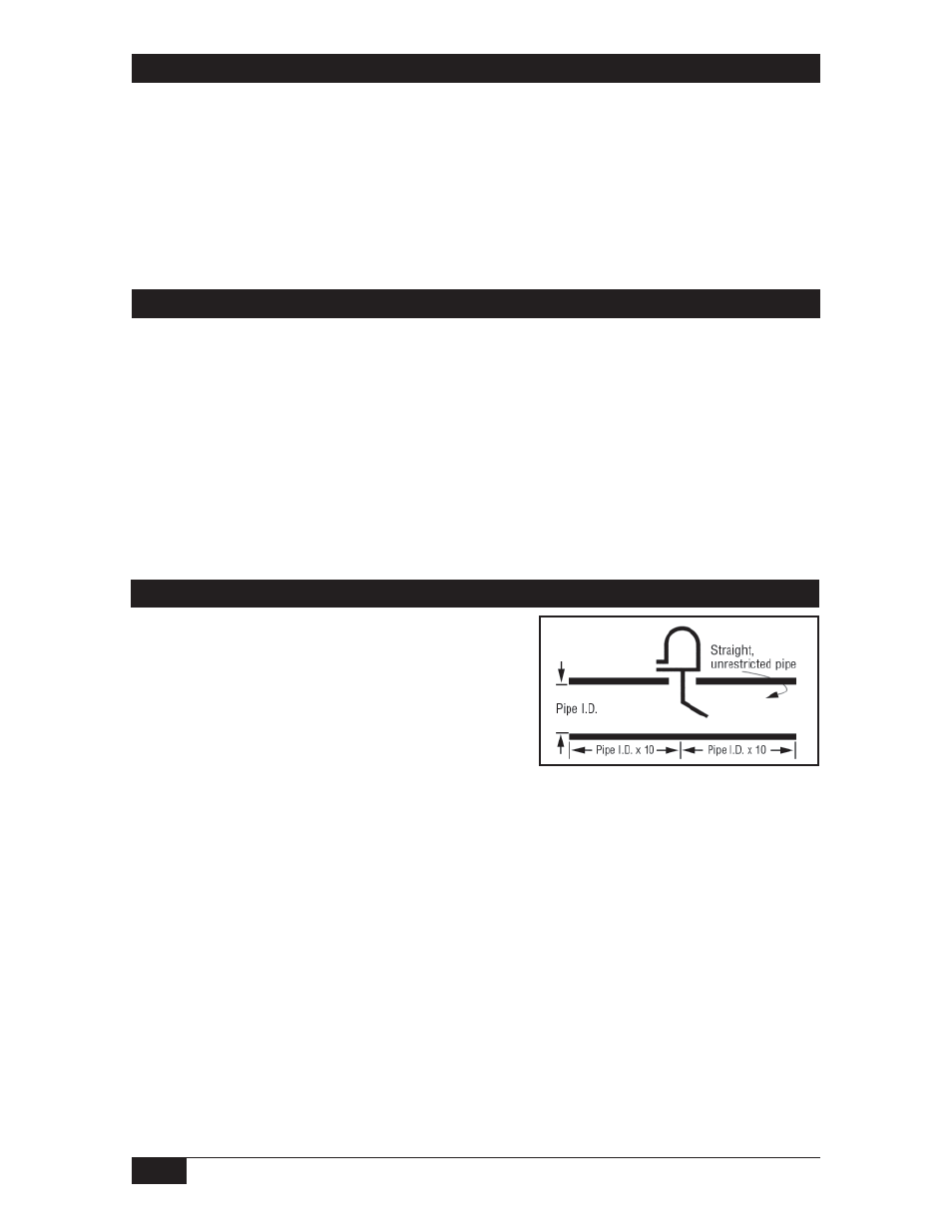
Integrally mounted controls should be mounted with
the vessel flange or nozzle within 3° of the vertical or
horizontal centerline of the vessel, as applicable.
Control should be mounted with ten diameters (pipe ID
x 10) length straight, unrestricted pipe on both sides.
Insulation of the control is not recommended.
Process Connection
Safety Integrity Level (SIL) Installation Requirements
The SOR pressure switches have been evaluated as Type-A safety related hardware.
To meet the necessary installation requirements for the SIL system, the following
information must be utilized:
Proof Test Interval shall be one year.
Units may only be installed for use in Low Demand Mode.
Products have a HFT (Hardware Fault Tolerance) of 0, and were evaluated in a
1oo1 (one out of one) configuration.
Form 1538 (03.12) ©2012 SOR Inc.
Installation
The unit may be mounted in any of the following installation arrangements:
a. 1-1/2 NPT half coupling (No full coupling.)
b. 2 NPT full coupling (Use in conjunction with 2 x 1-1/2” NPT bushing as required.)
c. 2 NPT pipe tee (Use in conjunction with 2 x 1-1/2” NPT bushing as required.)
d. Optional flanged mounting