SOR Single Diaphragm Weatherproof Differential Pressure Switch with Terminal Block Connections User Manual
Page 5
Form 506 (01.13) ©SOR Inc.
5/12
For Critical Set Point on Increasing Differential Pressure
Connect the continuity test lamp or ohmmeter across the C - Common and NO -
Normally Open switching element / contacts.
Close the bleed valve(s), open the equalizer valve and raise pressure equally on both HI
and LO sides to the static pressure that the differential pressure switch will see under
normal operating conditions.
With static pressure stable, close the equalizer valve to isolate the HI side from the LO
side.
Keeping high side pressure steady, slightly open the LO side bleed valve to reduce the
LO side pressure (increase differential pressure) until desired differential pressure set
point appears on indicator. Close bleed valve to stabilize differential pressure. Check the
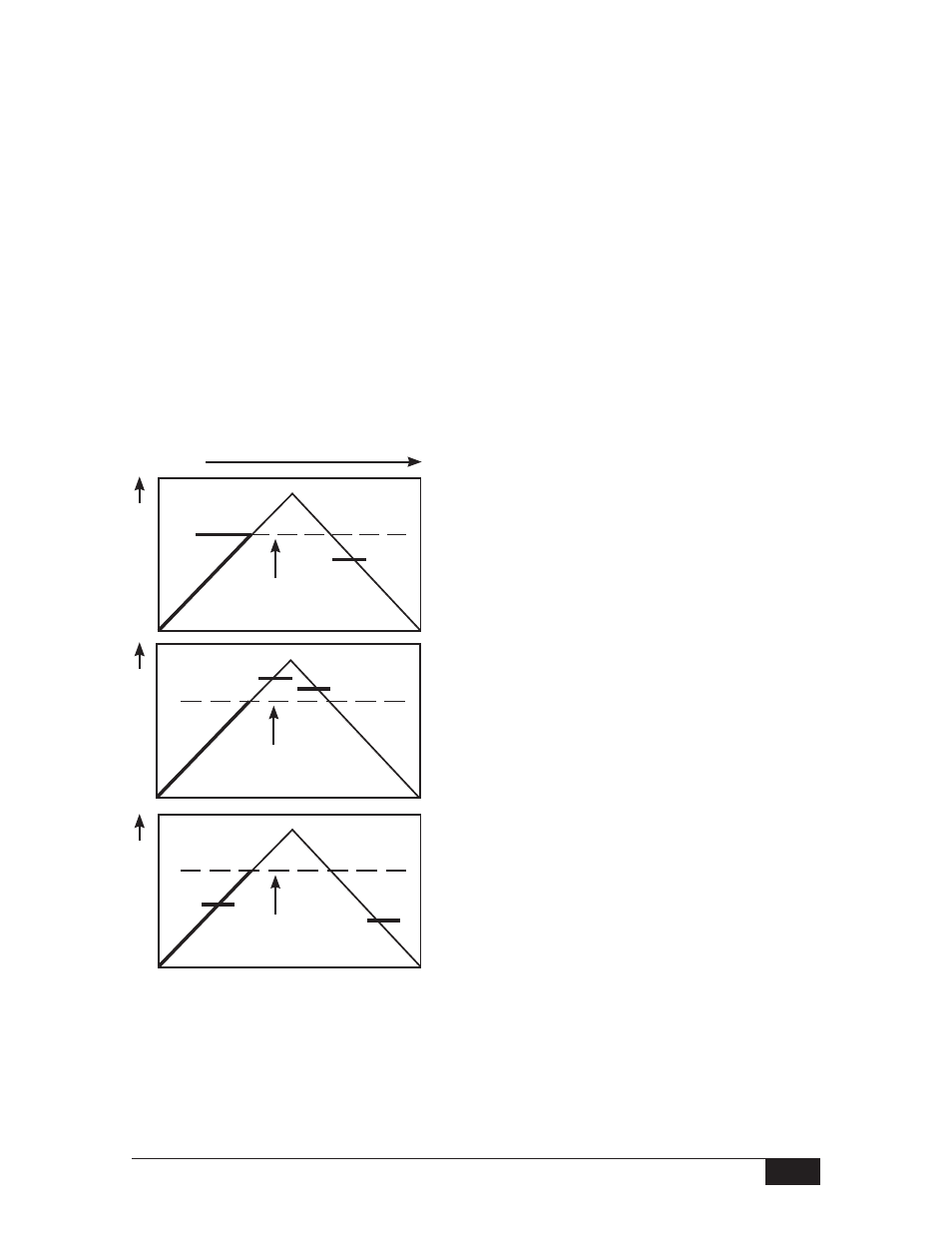
status of the electrical contacts against the following differential pressure trend graphs.
Follow the instructions under the graph that matches the status of the contacts.
If contacts make precisely at critical increasing
differential pressure set point, repeat Steps
-
as desired to verify calibration.
Calibration is complete.
If contacts are open when critical increasing
differential pressure is reached, turn set point
adjustment counterclockwise (out) until
contacts make. Repeat Steps
-
.
If contacts are closed when critical increasing
differential pressure is reached, turn set point
adjustment clockwise (in) until contacts break.
From this point, turn set point adjustment
counterclockwise (out) until contacts make.
Repeat Steps
-
.
Contacts Open - Set Point Too High
Set Point OK
Contacts Closed - Set Point Too Low
0 Time
Differential Pressure
Break
Make
Critical
Increasing
Set Point
Critical
Increasing
Set Point
Make
Break
Break
Make
Critical
Increasing
Set Point
See SOR Form 468 for reference dimension drawings. For certified dimension drawings
contact factory.
Differential Pressure
Differential Pressure