SOR 534CR Pressure Transmitter User Manual
Page 3
Form 903 (03.13) ©SOR Inc.
3/8
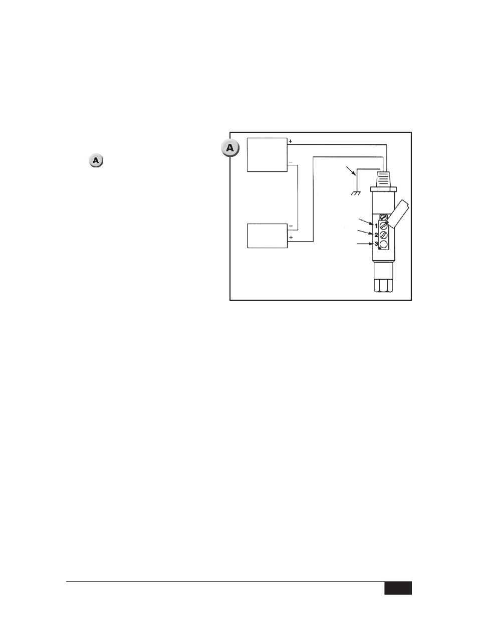
Power
Supply
10 - 30 VDC
milliammeter
4 - 20 mA
Red
Black
Case
Ground
Zero
Not Used
Span
Bare
Connect the transmitter as shown
in . Case ground must be
connected to earth ground to
ensure EMI/RFI protection.
Apply pressure at which 4 mA output
is desired. (Zero may be adjusted
±10% of the upper range limit.)
With pressure source steady at the
desired zero level, rotate the zero
adjustment (#1) for a 4 mA indication
on the milliammeter.
Apply pressure at which 20 mA out-
put is desired. Span may be adjusted
from 25 to 100% of the upper range limit. (Maximum turndown is 4:1.)
With pressure source steady at the desired span level, rotate the span adjustment (#2)
for a 20 mA indication on the milliammeter.
Repeat steps 2 through 5 as needed if offsetting 4 mA from the normal zero point.
If interaction occurs, turn zero and span 15 turns counterclockwise. Repeat steps 2
through 6 above.
Calibration Procedure
The zero and span calibration procedure should be performed under ambient process
temperature conditions.
A pressure source with a calibrated reference gage, a milliammeter and a DC voltage
supply are required. Note the adjustable range on the instrument nameplate. For both
zero and span adjustments, turn the adjustment screw clockwise to increase,
counterclockwise to decrease.