Plumbing and electric schematics – PermaGreen Triumph Spread-Only User Manual
Page 42
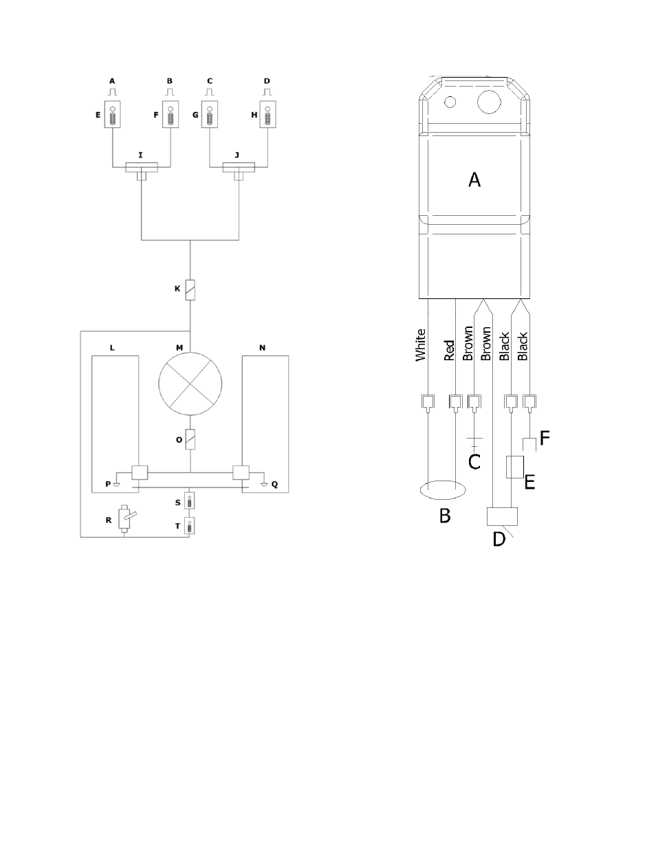
Plumbing and Electric Schematics
38
A) HIGH gear BROADCAST nozzle
B) HIGH gear TRIM nozzle
C) LOW gear BROADCAST nozzle
D) LOW gear TRIM nozzle
E) Nozzle body, cap and gasket, and strainer
F) Nozzle body, cap and gasket, and strainer
G) Nozzle body, cap and gasket, and strainer
H) Nozzle body, cap and gasket, and strainer
I)
Spray selector valve, HIGH gear
J) Spray selector valve, LOW gear
K) Spray control valve
L) Left 6-Gallon tank
M) Pump
N) Right 6-Gallon tank
O) Suction valve
P) Suction strainer
Q) Suction strainer
R) Fill valve and drain
S) Check valve
T) Pressure unloader valve
FIGURE 25, Plumbing Diagram
A) Starting module
B) Neutral switch
C) Ground to engine
D) Kill switch
E) Engine Magneto
FIGURE 26, Wiring Diagram
This manual is related to the following products: