Spreader operation 23 – PermaGreen Triumph Spread-Only User Manual
Page 27
Verify that the spreader discharge holes are closed.
If the spreader discharge holes are not completely closed, adjust
the length of the control cable running from the controls on the left
handlebar down the handle to the outer hopper control plate by
loosening and repositioning the locknuts.
If you did not purchase a calibration kit with your Triumph, obtain
the following materials:
Eleven collection pans, 3 to 4 INCHES (8 to 10 centimeters)
high and about 1 FOOT (0.3 meter) square (i.e., aluminum
roasting pans)
A clear graduated tube, 1/2-Inch (13 millimeter) internal
diameter, 3 to 4 INCHES (8 to 10 centimeters) tall (to act as a
graduated cylinder for measuring the collected fertilizer pellets)
Use a thin-tipped permanent marker to mark the tube at
QUARTER-INCH (6 millimeter) increments all the way up the
tube.
Clear, graduated ONE QUART (one liter) measuring cup
Stop watch or wristwatch.
This owner’s manual, and a pencil to record your collection
amounts.
Example Calibration procedure. IMPORTANT: The actual
settings for the fertilizer you are using will be different.
Establish the spreader Rate adjustment and calibration adjustment
for a fertilizer to be applied at the rate of 3 POUNDS / 1,000 ft
2
(1.36 Kg / 93 m
2
).
Place the spreader operating lever in the CLOSED position.
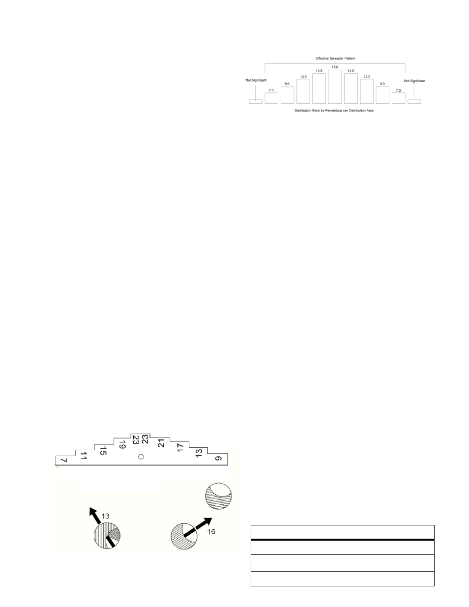
Open the Hopper and using the Calibration Gage (FIGURE 12)
provided with the machine as shown in FIGURE 13, set the
center hole opening to 16. Position the Rate Adjustment Knob
against the Hopper Lever and tighten the knob.
Close and open the Hopper several times and confirm hole
opening.
Adjust Third-hole setting.
Without changing the Rate Adjustment Knob setting, open
the Third-hole and insert the Calibration Gage, orientated as
shown in FIGURE 13, in the Third-hole.
Using the Third-hole Lever, position the Third-hole
Adjustment Plate against the Calibration Gage and position
the Memory-Lock until it pops into the Lever and locks its
position.
Remove the Calibration Gage.
Close and open the Third-hole several times and verify the
Third-hole setting is 13. Readjust as necessary.
Record both the Calibration Gage setting and the Memory-
Lock setting for future use. NOTE: The correct Calibration
Gage setting must be verified from time to time.
The Memory-Lock setting is adequate for reference in the
field, but it must be adjusted to the Calibration Gage during
the Daily machine Servicing.
Determine the effective spread width of the granular product:
Spreader Operation
23
Place 11 calibration pans in a line on two-foot centers on a
paved area such as a parking lot. NOTE: Checking the
effective spread pattern and adjusting the distribution
pattern requires multiple passes over the calibration pans.
This process is done on a paved area to avoid burning the
vegetation by over-fertilizing, and to allow the product to be
collected and reused.
With the material to be spread loaded in the spreader, make
at least three passes from the same direction over the pans
in a path perpendicular to the line of pans while spreading
material.
Pour the contents of the first pan on your far left into the
graduated cylinder or clear tube. Measure and record the
material deposited. Dump the collected pellets back into the
bag or hopper. Repeat this measurement for each pan, one
by one, until all eleven pans are emptied and recorded.
The distribution pattern should be balanced as in FIGURE
13A with a higher amount of product, collected in the
center pan and tapering off equally to both sides. NOTE:
The distribution pattern shown in FIGURE 13A represents
an ideal pattern, which will not be reproducible in the field.
The numbers are used for reference only.
To balance the distribution pattern for the right side, move
the lever as necessary to increase or decrease the opening
in the adjustment hole. Reset the memory lock.
Repeat the passes over the pans and measure the material
deposited in the pans. Readjust the openings as necessary
until the distribution pattern meets the requirements.
The effective spread width is the measured distance
between the left and right pans that contain 50% of the
volume of the center pan.
Record each opening setting for future recalibration.
Determine the Rate Adjustment Knob setting which delivers
the desired amount of fertilizer for the calibrated effective
spreader width (above) for both HIGH GEAR and LOW GEAR
speeds.
Measure AND RECORD the amount of time it takes to
spread 1,000 ft
2
(93 m
2
) of area. NOTE: The machine is
designed to operate at a full throttle engine speed of 3450
RPM while in NEUTRAL. Check engine speed with the
tachometer and adjust to 3450 RPM if needed (see
Adjusting Engine speed to 3450 RPM in the Service
Manual section). Keeping the engine speed constant,
helps insure that the application rate remains constant.
Create a test course based on the effective Spread Width
from the table above. EXAMPLE:
Triumph comes set from the factory to an effective
spread and spray width of 7 FEET, which can be
accomplished by making
7 FOOT center-to-center
parallel passes overlapping approximately 50
PERCENT of the last pass
. Measure a distance
equal to the of 143 FEET (44 meters) over turf. This will
provide a spread area of approximately 1,000 ft
2
(93
m
2
). The effective material spread width for many
products is 7 FEET; therefore, 7 x 143 = 1,001 ft
2
(93
m
2
). NOTE: If your calibrated effective spread width
is 8 feet, you will use 8 x 125 = 1000 ft
2
as the basis for
Length of a 1,000 Square Foot calibration course
Effective Spread Width
Length of Course
7
143
8
125
FIGURE 13A, Spread distribution
FIGURE 13, Spreader Setting
FIGURE 12, Calibration Gauge