Cylinder slide adjustment – Parr Instrument Series 4558 User Manual
Page 13
4555 - 58 Series
5G & 10L Pressure Reactors
- 12 -
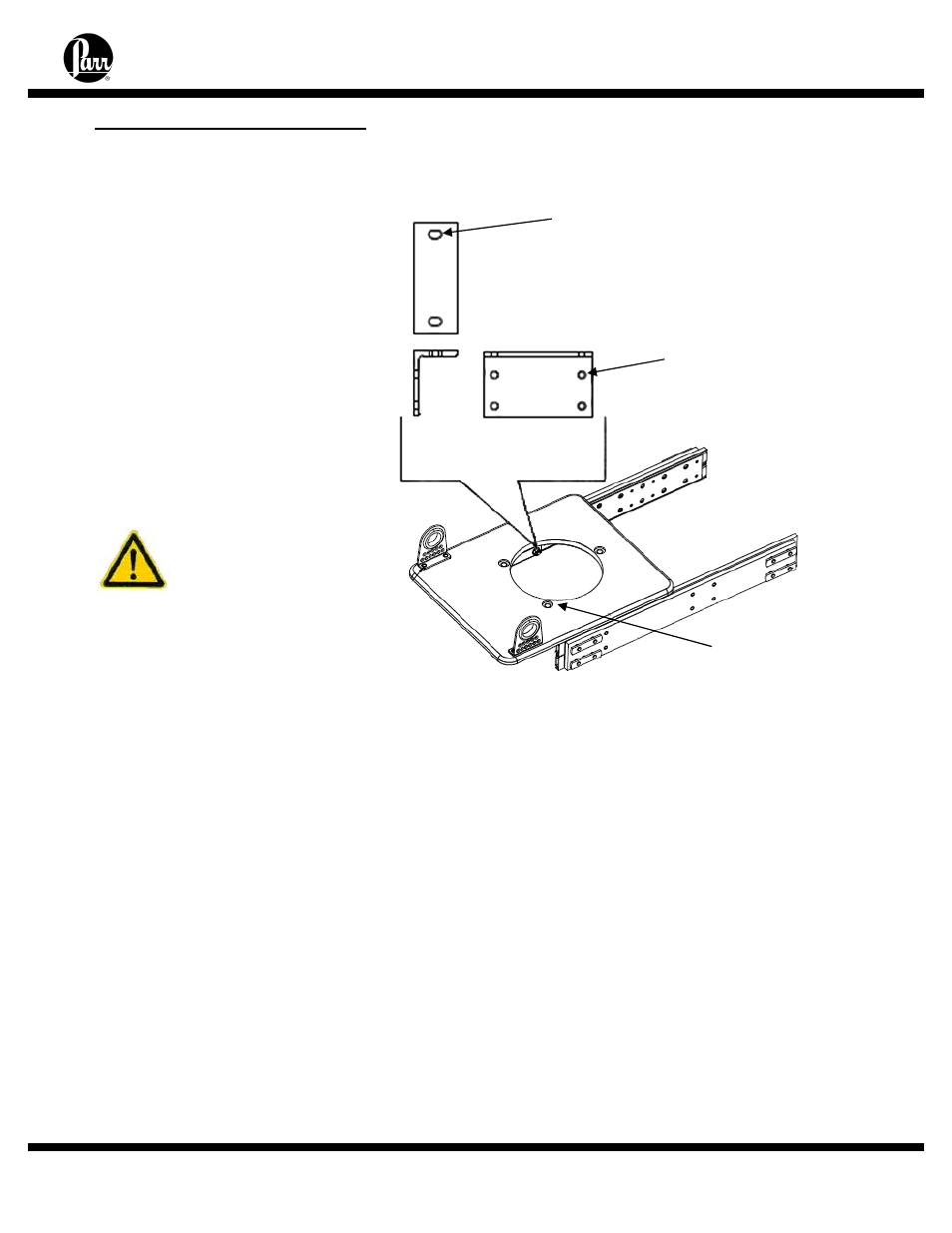
Slotted holes for
center adjustment
(Left/Right)
(4) 5/16 x 1/2”
Oversized holes for
level adjustment
(Sagging)
(4) 5/16 x 3/4” Bolts
Holes for
cylinder
mounting
(3) 3/8” Nuts and
Flat Washers
Cylinder Slide Adjustment
Minimal, if any, adjustments
are required for binding or sagging
of the cylinder slide support.
Note: To adjust for sagging, the
cylinder must be removed from the
Slide Support. This can be done
by leaving the closure intact with
the head and cylinder and
removing the (3) 3/8” nuts from the
bottom of the cylinder standoffs.
Lower the support stand
accordingly. This may require
removal of any plumbing devices
or accessories located on the
bottom of the cylinder.
Caution: The
cylinder is very
heavy and caution
should be
observed when the
cylinder is
disconnected from
the Slide Support.
1. Any adjustments to the Slide Support must be made with the Slider Support in the “IN”
position. Adjustments in the “OUT” position can cause unwanted binding to occur.
2. Once the (3) nuts have been removed from the bottom of the Slide Support, the Slide
Support can be lowered. It can then be leveled by loosening the Angle Support Brackets
detailed in the figure F1. Gently loosen the (8) horizontally mounted 5/16 x ¾” fasteners on
the Angle Support Brackets and adjust the Cylinder Support until it is level. Then tighten the
(8) 5/16 x ¾” fasteners accordingly.
3. Loosen the (4) 5/16 x ½” vertically mounted fasteners on the Angle Support brackets
until the support bracket moves freely. Center (left to right) the Slide Support and ensure
that there is no excessive force being applied against or away from the slide rails. Then
tighten the (4) fasteners accordingly.
4. Raise the Slide Support to the bottom of the cylinder until the standoffs are inserted into
the holes provided on the Slide Support. Attach the Slide Support to the cylinder using the
3/8” nuts previously removed.