2 condensation of the vapours in a cooling trap – Martin Christ RVC 2-18 CDplus User Manual
Page 27
RVC 2-18 CD&
5 Set-up and connection
Version 04/2012, Rev. 1.3 of 25/11/2013 • sb
27
Translation of the original operating manual
Pos: 97 / 200 Christ /37 1 RVC-BA (PROJEKTE) /RVC 2-1 8 CDpl us_2 -18 CD plus_HCl /050 Aufstell ung und Anschluss /05 0-0 060 -00 20 Ko nde nsati on d er anfalle nde n Dä mpfe üb er ei ne Kü hlfalle @ 9\ mod _13 2065 736 377 6_6 8.do cx @ 5 399 5 @ 3 @ 1
5.5.2
Condensation of the vapours in a cooling trap
The vapours are condensed upstream of the vacuum pump in a cooling
trap, e.g.”CT 02-50” or “CT 04-50”.
The application is suitable for water-base, low-boiling samples containing
solvents. The RVC, the cooling trap and the vacuum pump must be
connected. The connector of the stop valve must be plugged into the
socket on the back of the unit.
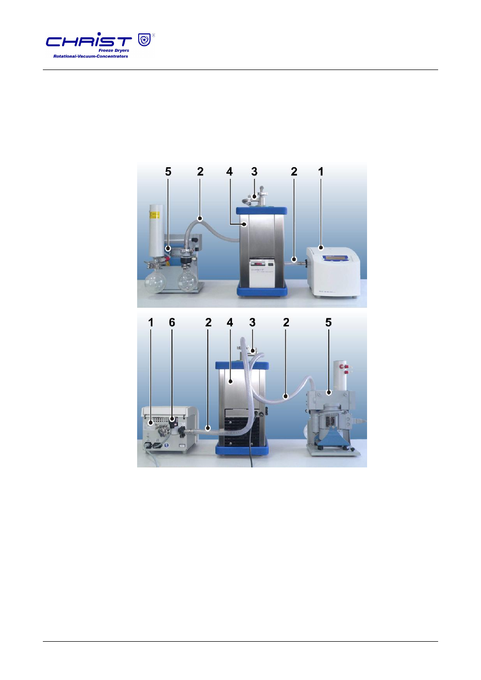
1
RVC
2
Vacuum hoses
3
Cover with connecting
hoses
4
Cooling trap
5
Vacuum pump
6
Electromagnetic stop
valve
Fig. 7: Combination of the RVC with vacuum pump and cooling trap, front and rear view
Pos: 98 / 010 Unive rsalm odul e/ L ee rzeile @ 0\ mod _120 211 624 450 0_0. docx @ 11 4 @ @ 1
Pos: 99 / 200 Christ /37 1 RVC-BA (PROJEKTE) /RVC 2-1 8 CDpl us_2 -18 CD plus_HCl /050 Aufstell ung und Anschluss /05 0-0 070 Elektr oma gne tisches Abspe rrv entil @ 19\ mod _13 793 9646 540 2_6 8.do cx @ 9505 1 @ 4 @ 1