Ab c, Page 18 – Lingenfelter L460285297 & L460316109 Lingenfelter LNC-TRM Torque Reduction Module v1.2 User Manual
Page 19
Page 18
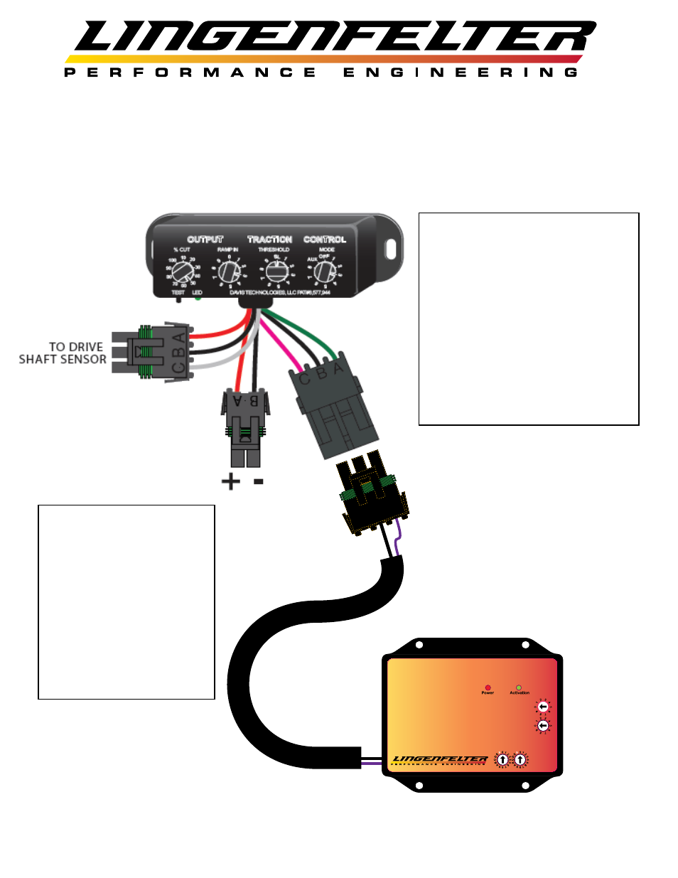
LNC-TRM Recieving 0-5V Timing Retard Input from a Davis
Technologies TMS-Drag-MAP Series Traction Control Module
(Without the MAP Adapter)
A
B
C
Purple = 0-5 Volt Analog Input
Black = Ground
Red = +5 volt
Gray = 0-5 volt out, Applied Retard
Yellow = +12V Activation
Green = Ground Activation
Torque Reduction Module
LNC-TRM
0 = 25mS
1 = 30mS
2 = 35mS
3 = 40mS
4 = 45mS
5 = 50mS
6 = 55mS
7 = 60mS
8 = 65mS
9 = 70mS
A = 75mS
B = 80mS
C = 85mS
D = 90mS
E = 95mS
F = OFF
Kill Time
Kill Time
Retard Slope
Max Retard
0 = Full Authority
1 = 2 Degree
2 = 4 Degree
3 = 6 Degree
4 = 8 Degree
5 = 10 Degree
6 = 15 Degree
7 = 20 Degree
8 = 25 Degree
9 = 30 Degree
Retard Slope
0 = 5 Degrees
1 = 10 Degrees
2 = 15 Degrees
3 = 20 Degrees
4 = 25 Degrees
5 = 30 Degrees
6 = 35 Degrees
7 = 40 Degrees
8 = 45 Degrees
9 = 50 Degrees
Max Retard
Kill Time
Adder
0 = 0mS
1 = 10mS
2 = 20mS
3 = 30mS
4 = 40mS
5 = 50mS
6 = 60mS
7 = 70mS
8 = 80mS
9 = 90mS
A = 100mS
B = 110mS
C = 120mS
D = 130mS
E = 140mS
F = 150mS
Kill Time
Adder
Total Time = Adder + Kill Time
130mS = (5)50mS + (B)80mS
B
C
A
• Using a 3 pin Weather Pack
connector (PN 12015793) and pins,
connect the 0-5 Volt analog input
(purple wire) on the LNC-TRM to
the 0-5 Volt output from the TMS
(green wire, pin A).
• Connect the black ground wire on
the LNC-TRM to the black ground
wire on the TMS (pin B).
• DO NOT connect the red 5 Volt wire
from the LNC-TRM (use a cavity
plug to seal that position in the
connector).
• Set the traction control
module for the desired
timing retard ramp.
• Set the Max Retard setting
on the LNC-TRM.
• Set the Retard Slope on the
LNC-TRM.
• While the traction control
module will create the
timing retard ramp, the
LNC-TRM will still control
the maximum timing retard.